
Installation Sheet
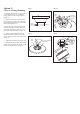
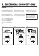
Table Of Contents

5. ELECTRICAL CONNECTIONS
Fig. 12 Fig. 12a Fig. 12b
Outlet box
Fan switch
on wall
Ceiling
REMEMBER -Turn off the power!
WH
BLUE
BLK
WH
BLK
House
supply
wire
GROUND
GRN
3. Optional Wall Controls:
Wiring connections for optional wall
control are shown in Fig. 12a and 12b.
Figure 8a shows how to wire a fan wall
control switch. This controls the fan only.
To separately control an optional light kit
using the light kit pull chain, you would
have to connect the blue wire from the fan
to the house supply wire, before it goes to
the wall control. This is not an easy
connection, and we suggest you call a
qualified electrician to do it for you.
4. Inside the ceiling junction box be sure
to spread the wires apart so that the black
and blue connections are on one side of
the outlet box and the white/white and
green/ copper connections are on the other
side.
Use the wire nuts supplied with your fan
when making connections. Secure the
connectors with electrical tape and make
sure there are no loose connections or wire
strands.
1. Spread the wires apart so that the black
and blue wires from the fan are on one
side of the mounting bracket and the white
wire and green ground wire are on the
other side.
2. (Fig. 12) Connect the BLACK building
supply wire to the BLACK and BLUE fan
wires. Connect the WHITE building
neutral wire to the WHITE fan neutral
wire. Connect the COPPER building
ground wire to the GREEN fan ground
wire.
Use ONLY wall controls approved by
Quorum. Use of unapproved wall
controls will cause unacceptable
humming noise, and avoids the fan
warranty.
Outlet box
Ceiling
WH
BLUE
BLUE
BLUE
BLK
WH
BLK
BLKBLK
GROUND
GRN
Fan/light
switch
on wall
House
supply
wire
Outlet box
Ceiling
WH
BLUE
BLUE
BLUE
BLK
WH
BLK
BLK
BLKBLK/WH
GROUND
GRN
Fan Fan Fan