Installation and Operation Manual ASM-60 4-Wire Symmetrical VDSL Modem
ASM-60 4-Wire Symmetrical VDSL Modem Installation and Operation Manual Notice This manual contains information that is proprietary to RAD Data Communications Ltd. ("RAD"). No part of this publication may be reproduced in any form whatsoever without prior written approval by RAD Data Communications.
Limited Warranty RAD warrants to DISTRIBUTOR that the hardware in the ASM-60 to be delivered hereunder shall be free of defects in material and workmanship under normal use and service for a period of twelve (12) months following the date of shipment to DISTRIBUTOR.
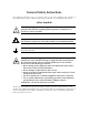
General Safety Instructions The following instructions serve as a general guide for the safe installation and operation of telecommunications products. Additional instructions, if applicable, are included inside the manual. Safety Symbols Warning This symbol may appear on the equipment or in the text. It indicates potential safety hazards regarding product operation or maintenance to operator or service personnel.
Handling Energized Products General Safety Practices Do not touch or tamper with the power supply when the power cord is connected. Line voltages may be present inside certain products even when the power switch (if installed) is in the OFF position or a fuse is blown. For DC-powered products, although the voltages levels are usually not hazardous, energy hazards may still exist.
Connection of Data and Telecommunications Cables Data and telecommunication interfaces are classified according to their safety status. The following table lists the status of several standard interfaces. If the status of a given port differs from the standard one, a notice will be given in the manual. Ports Safety Status V.11, V.28, V.35, V.36, RS-530, X.
Caution Attention To reduce the risk of fire, use only No. 26 AWG or larger telecommunication line cords. Pour réduire les risques s’incendie, utiliser seulement des conducteurs de télécommunications 26 AWG ou de section supérieure. Some ports are suitable for connection to intra-building or non-exposed wiring or cabling only. In such cases, a notice will be given in the installation instructions. Do not attempt to tamper with any carrier-provided equipment or connection hardware.
Canadian Emission Requirements This Class A digital apparatus meets all the requirements of the Canadian Interference-Causing Equipment Regulation. Cet appareil numérique de la classe A respecte toutes les exigences du Règlement sur le matériel brouilleur du Canada. Warning per EN 55022 (CISPR-22) Warning This is a class A product. In a domestic environment, this product may cause radio interference, in which case the user will be required to take adequate measures.
ASM-60 with IR-ETH/QH Interface Module Installation Instructions for Compliance with EMC Requirements To comply with electromagnetic compatibility requirements, use a shielded cable (STP) for connecting a 10/100BaseT LAN to the RJ-45 connector of the IR-ETH/QH interface module.
Declaration of Conformity Manufacturer's Name: RAD Data Communications Ltd. Manufacturer's Address: 24 Raoul Wallenberg St. Tel Aviv 69719 Israel declares that the product: ASM-60 Product Name: conforms to the following standard(s) or other normative document(s): EMC: Safety: EN 55022: 1998 Information technology equipment, radio disturbance characteristics, limits and methods of measurement.
Quick Start Guide Installation of ASM-60 should be carried out only by an experienced technician. If you are familiar with ASM-60, use this guide to prepare the units for operation. 1. Installing ASM-60 Setting the Internal Switches To set internal switches: 1. Disconnect the power cord from the power source. 2. Slide the blue side panel forward to detach it from the case. 3. Unscrew the two screws located on the bottom panel at the rear end of the unit. 4.
ASM-60 Installation and Operation Manual Quick Start Guide 2. Operating ASM-60 Normal Indications The table below shows the correct status of the indicators a few seconds after power-up. 3.
Contents Chapter 1. Introduction 1.1 Overview..................................................................................................................... 1-1 Versions................................................................................................................................ 1-1 Application ........................................................................................................................... 1-1 Features........................................................
Table of Contents Chapter 5. Diagnostics 5.1 Error Detection ............................................................................................................ 5-1 Power-Up Self-Test ............................................................................................................... 5-1 Front-Panel LEDs .................................................................................................................. 5-1 Alarms ...........................................................
Table of Contents List of Figures 1-1. Typical ASM-60 Application .................................................................................................. 1-1 1-2. 3D View of ASM-60 .............................................................................................................. 1-3 1-3. ASM-60 Block Diagram ......................................................................................................... 1-4 2-1 Rear Panel of ASM-60 with HSSI Interface........................
Table of Contents iv ASM-60 Installation and Operation Manual
Chapter 1 Introduction 1.1 Overview ASM-60 is a VDSL (Very High-bitrate Digital Subscriber Line) modem handling high data rates. ASM-60 supports HSSI DTE interface, and several Ethernet interface modules, which allow LAN-to-LAN connectivity using VDSL technology. Working in full duplex over 4-wire link, the modem can be configured to operate at the data rates of up to 10.240 Mbps.
ASM-60 Installation and Operation Manual Chapter 1 Introduction Features ASM-60 utilizes the QAM VDSL technology to extend the range of data transmission over 4-wire 24 AWG line up to 2.0 km (1.2 miles). ASM-60 operates at the following data rates: 4.096 Mbps, 6.144 Mbps and 10.24 Mbps. Table 1-1 lists typical ASM-60 ranges over 24 AWG STP Cat. 5 wire. Table 1-1. Typical ASM-60 Ranges Data Rate 24 AWG (Mbps) km miles 4.096 2.0 1.2 6.144 2.0 1.2 10.24 1.8 1.
ASM-60 Installation and Operation Manual Chapter 1 Introduction 1.2 Physical Description Figure 1-2 shows a 3D view of the ASM-60 standalone modem. Figure 1-2. 3D View of ASM-60 The front panel includes nine LEDs, which display the status of power, data flow, control signals and provide diagnostics. The front panel also features a 9-pin D-type (CONTROL DCE) connector for terminal connection for configuration, control and monitoring. For detailed description of the front panel, see Chapter 3.
ASM-60 Installation and Operation Manual Chapter 1 Introduction 1.3 Functional Description This section provides a functional description (Figure 1-3) of ASM-60 in the form of block diagrams. TxD, RxD A11-A15 CPU INT, EXT Clock DTE Interface RS-232 Data, Clock Additional Decoder A0-A7, A14 D8-D15 EVM1 VDSL Framer HYBRID1 TRANSF.1 VDSL Line Interface Data, Clock EVM2 HYBRID2 Line A Line B TRANSF.2 Latch/Buffer 3.3V 5.0V LEDs AC Power Supply Control Figure 1-3.
ASM-60 Installation and Operation Manual Chapter 1 Introduction 1.4 Technical Specifications Line Interface Protocol Very High-bit-rate Digital Subscriber Line (VDSL) Type 4-wire, unconditioned dedicated lines (twisted pair), Cat.3 and Cat.5, 19 AWG to 26 AWG Line Coding QAM Range See Table 1-1 Levels 11 dBm Impedance 110Ω Return Loss More than 15 dB Carrier Constantly On DTE Interface Data Rate Type User-selectable: 4.096 Mbps, 6.144 Mbps or 10.
ASM-60 Installation and Operation Manual Chapter 1 Introduction Indicators Physical PWR (green) Power RTS (yellow) Request to Send TD (yellow) Transmit Data RD (yellow) Receive Data DCD (yellow) Data Carrier Detect TST (red) Test ALM (red) Alarm SYNC A (green/red) Synchronization line A SYNC B (green/red) Synchronization line B Height Width 215 mm / 8.5 in Depth 243 mm / 9.6 in Weight Power 1 kg / 3.
Chapter 2 Installation and Setup This chapter describes installation and setup procedures for the standalone ASM-60 modem. ASM-60 is delivered completely assembled. It is designed for tabletop or 19-inch rack installation. After installing the unit: • Refer to Chapter 3 for the operating instructions. • Refer to Chapter 4 for the detailed system configuration procedures using ASCII terminal connected to the ASM-60 control port.
Chapter 2 Installation and Setup ASM-60 Installation and Operation Manual 2.2 Package Contents The ASM-60 package includes the following items: • One ASM-60 unit • Last Mile Access and Intelligent Modems CD • AC power cord • RM-28 rack installation kit (if ordered). 2.3 Installation and Setup The ASM-60 standalone unit is designed for desktop installation and is delivered as a fully assembled unit. No provisions are made for bolting the unit to a tabletop. To install ASM-60: 1.
ASM-60 Installation and Operation Manual Chapter 2 Installation and Setup Opening the ASM-60 Case To open the ASM-60 case: 1. Disconnect the power cord from the power source. 2. Slide the blue side panel forward to detach it from the case. 3. Unscrew the two screws located on the bottom panel at the rear end of the unit. 4. Separate the two halves of the ASM-60 case by lifting the top cover at the end of the unit and sliding it forward.
ASM-60 Installation and Operation Manual Chapter 2 Installation and Setup Connecting the DTE The ASM-60 DTE interface provides interface for input/output data, clock reference and control signals between the modem and the DTE. The ASM-60 DTE interface can be either HSSI interface module, terminating in SCSI 50 female connector (see Table 2-2), or one of the Ethernet interface modules, described in greater detail in Appendix A, Appendix B and Appendix C.
ASM-60 Installation and Operation Manual Chapter 2 Installation and Setup Connecting the Power Warning Before switching on this unit and connecting any other cable, the protective earth terminals of this unit must be connected to the protective ground conductor of the power cord. If you are using an extension cord (power cable) make sure it is grounded as well.
Chapter 2 Installation and Setup 2-6 Installation and Setup ASM-60 Installation and Operation Manual
Chapter 3 Operation This chapter provides the description of the ASM-60 front-panel indicators, and details the modem's operating procedures (turn-on, front-panel indications, performance monitoring and turn-off). Installation procedures given in Chapter 2 must be completed and checked before attempting to operate ASM-60. 3.1 Front Panel Indicators The front panel of ASM-60 includes nine LED indicators that show the current operating status of the unit.
ASM-60 Installation and Operation Manual Chapter 3 Operation Table 3-1. LED Indicators (Cont.) Name Function SYNC A (red/green) ON (red) – Data link A is not synchronized with the remote modem ON (green) – Data link A is synchronized with the remote modem SYNC B (red/green) ON (red) – Data link B is not synchronized with the remote modem ON (green) – Data link B is synchronized with the remote modem 3.
Chapter 4 Management from a Terminal The configuration of ASM-60 is performed via menu-driven embedded software using a standard ASCII terminal or a PC running a terminal emulation application connected to the front panel CONTROL DCE port. This terminal can be used for performing the following management activities supported by ASM-60: • Modifying setup configuration • Monitoring of device status and settings • Collect performance statistics • Restarting ASM-60. 4.
ASM-60 Installation and Operation Manual Chapter 4 Management from a Terminal Table 4-1. Control Port Control Signals Control Line Interface Type DCE DTE CTS Out Not Used DCD Out Out DSR Out Out DTR In In RI Not Used In RTS In In Data Terminal Ready (DTR) When connected and turned on, the terminal sets the DTR line ON (active) to gain control over ASM-60 and starts a configuration or monitoring session. Initiating a Control Session To initiate a control session: 1.
ASM-60 Installation and Operation Manual Chapter 4 Management from a Terminal Terminal Management Menus Figure 4-1 shows a map of the management menus in the ASM-60 embedded software. The second level menus (Configuration, Display, Reset) are described in its own section in this chapter. The Alarms, Log File, VDSL Performance and Test menus are described in Chapter 5. Main Menu 1. Configuration 1. Data Rate 1. 4096 kbps 2. 6144 kbps 3. 10240 kbps 2. Display 1. Status 3. Test 4. Reset 1.
ASM-60 Installation and Operation Manual Chapter 4 Management from a Terminal ASM-60/CO Main Menu 1. Configuration 2. Display 3. Test 4. Reset 5. Debug > ESC - previous menu ; ! - main menu ; & - exit terminal ------------------------------------------------------- Figure 4-2. Main Menu Note At the bottom of the terminal screen, ASM-60 displays the latest alarms as they enter the alarm log. 4.4 Configuring ASM-60 This section describes the configuration procedures for the ASM-60 modem.
ASM-60 Installation and Operation Manual Chapter 4 Management from a Terminal Data Rate (current value) Enter the Devise Bit Rate 1. 4096 kbps 2. 6144 kbps 3. 10240 kbps > ESC - previous menu ; ! - main menu ; & - exit terminal ------------------------------------------------------- Figure 4-4. Data Rate Menu 4.5 Displaying the ASM-60 System Information The ASM-60 software allows to display the modem system information. To access the Display menu: • From the Main menu, type 2.
ASM-60 Installation and Operation Manual Chapter 4 Management from a Terminal Displaying the ASM-60 Status Main Menu ↓2 Display ↓1 Status You can display the current status of the local and remote ASM-60 modems. To display the ASM-60 status: • From the Display menu, type 1. The Status screen is displayed (see Figure 4-6). Status Device Rate: 6144 kbps Remote Status: ASM60/SA CO Active Software Version: 01.00 Hardware Version (PCB): 00 AFE Version: 00.
ASM-60 Installation and Operation Manual Chapter 4 Management from a Terminal 4.6 Resetting ASM-60 You can perform reset of the main components of ASM-60, or reset the modem to its factory settings. To reset ASM-60: 1. From the Main menu, type 4. The Reset menu appears (Figure 4-7). 2. From the Reset menu, choose one of the following: 1 – To reset ASM-60 to the default data rate – 10.240 kbps. 2 – To reset the ASM-60 CPU (if the Watchdog jumper on the V-Agent board is set to ON).
Chapter 4 Management from a Terminal 4-8 Resetting ASM-60 ASM-60 Installation and Operation Manual
Chapter 5 Diagnostics This chapter describes the ASM-60 diagnostic functions, which include: • Status indications, alarms, power-up self-test • VDSL performance diagnostics • LED testing. 5.1 Error Detection This section explains how to detect and fix errors and other problematic conditions in ASM-60. Power-Up Self-Test ASM-60 performs a hardware self-test upon turn-on. The self-test sequence checks the critical circuit functions of the modem.
ASM-60 Installation and Operation Manual Chapter 5 Diagnostics Alarms DCD Failed > ESC - previous menu ; ! - main menu ; & - exit terminal ------------------------------------------------------- Figure 5-1. Alarms Screen The display of the Alarms screen includes only the name of the alarm. Once the event that caused the alarm is cleared, the ALM indicator turns off.
ASM-60 Installation and Operation Manual Chapter 5 Diagnostics Table 5-1.
ASM-60 Installation and Operation Manual Chapter 5 Diagnostics VDSL Performance Line A Lock Status: SYNC Line A Avg. Snr.: 34 Line A BER pre FEC: 0.000E+00 Line A BER after FEC: 0.000E+00 Line B Lock Status: SYNC Line B Avg. Snr.: 34 Line B BER pre FEC: 0.000E+00 Line B BER after FEC: 0.000E+00 > ESC - previous menu ; ! - main menu ; & - exit terminal ------------------------------------------------------- Figure 5-3.
ASM-60 Installation and Operation Manual Chapter 5 Diagnostics 5.3 Running the Diagnostic Tests Running the LEDs Test The ASM-60 modem can perform the front-panel indicators test to verify that the unit LEDs are functioning properly. Main Menu ↓3 Test ↓2 Start LEDs Test To run the LEDs test: 1. From the Main menu, type 3. The Test menu appears. 2. From the Test menu, type 2 to run the LEDs test on ASM-60. All the front-panel LED indicators light up for 3 seconds.
Chapter 5 Diagnostics 5-6 Running the Diagnostic Tests ASM-60 Installation and Operation Manual
Appendix A IR-ETH Interface Module IR-ETH is an interface module for RAD modems, used for converting the Ethernet (10BaseT or 10Base2) electrical levels to the modem TTL levels. It also converts the Ethernet protocol to HDLC to enable long-distance transmission and avoid the Ethernet collision limitation. IR-ETH includes an internal, self-learning Ethernet bridge, which enables a high performance link between two Ethernet segments at a low transmission rate.
ASM-60 Installation and Operation Manual CAUTION : FOR CONTINUED PROTECTION AGAINST RISK OF FIRE, REPLACE ONLY WITH SAME TYPE AND RATING OF FUSE. LINE 10BASE-2 RX 100-230 VAC 0.250A T 250V Appendix A IR-ETH Interface Module COLL A-1 2 TX 4 5-B Figure A-3. Rear Panel of ASM-60 with IR-ETH Module (BNC Connector) Table A-1. RJ-45 Pinout Pin Function 3 RCV (+) 6 RCV (-) 1 XMT (+) 2 XMT (-) – GND A.
ASM-60 Installation and Operation Manual Appendix A IR-ETH Interface Module A.3 Installation and Operation Figure A-4 shows the Ethernet bridge layout, the location of the DIP switch, and the rear panel components of the IR-ETH interface module with RJ-45 connector. Figure A-4. IR-ETH Layout (UTP Option) DIP Switch Settings Table A-2 describes functions and default settings of the DIP switch SW-1 sections. Table A-2.
ASM-60 Installation and Operation Manual Appendix A IR-ETH Interface Module LED Indicators Table A-3 lists the IR-ETH LED indicators and describes their functions. Table A-3.
Appendix B IR-ETH/QH Interface Module B.1 Introduction The IR-ETH/QH interface module includes a high performance self-learning Fast Ethernet bridge, which is connected to the LAN via a single 10BaseT or 100BaseT port, operating in full duplex and providing offer simple and cost-effective interconnection between 10/100BaseT LANs via VDSL links. The IR-ETH/QH interface module also supports IEEE 802.1/Q frames, enabling VLAN applications.
ASM-60 Installation and Operation Manual Appendix B IR-ETH/QH Interface Module Table B-1. RJ-45 Connector Pinout Pin Signal Function 1 RD (+) Receive Data (positive) 2 RD (-) Receive Data (negative) 3 TD (+) Transmit Data (positive) 6 TD (-) Transmit Data (negative) B.3 Technical Specifications Bridge LAN LAN Table 1,000 MAC addresses Aging 5 minute, automatic Filtering and Forwarding Rate 150,000 packets per second Buffer Size 170 frames Delay 1 frame Standard IEEE 802.
ASM-60 Installation and Operation Manual Appendix B IR-ETH/QH Interface Module Setting the DIP Switch Configure the IR-ETH/QH module by setting the DIP switch in accordance with Table B-2. The DIP switch is located on the reverse side of the IR-ETH/QH module. To change the switch settings, you must undo three screws on the board and detach the module from the main unit. Table B-2.
Appendix B IR-ETH/QH Interface Module ASM-60 Installation and Operation Manual Connecting the LAN Use either a straight cable or a cross cable for the LAN connection. Use a cross cable when connecting to a port that does not implement the crossover function internally. Otherwise, use a straight cable. Note B-4 Hubs usually implement the crossover function internally, while NICs and other devices do not.
Appendix C IR-IP Interface Module C.1 Introduction Overview IR-IP is a high-performance, miniature IP router based on RAD's unique IP router chip, the ChipRouter. IR-IP works by taking each Ethernet frame from the LAN and determining whether the IP packet is destined for the IP net on the Ethernet LAN. If not, IR-IP forwards the packet to the WAN (line) link. IP packets received from the WAN link are automatically forwarded to the LAN if the IP net matches.
ASM-60 Installation and Operation Manual Appendix C IR-IP Interface Module Application Figure C-1 shows a typical application of the ASM-60 modem equipped with the IR-IP interface module. ASM-60 with IR-IP ASM-60 with V.35 Interface Router Figure C-1. Typical Application of ASM-60 with IR-IP C.
ASM-60 Installation and Operation Manual Appendix C IR-IP Interface Module IR-IP LEDs IR-IP contains three LEDs, which indicate the module activity. Table C-1 lists the LEDs functions. Table C-1. IR-IP LEDs Functions Name Type Function INT Green LED ON – LAN integrity is established. ACT Yellow LED Blinks – Transmit/receive activity is detected on the Ethernet link. ERR Red LED ON – Buffer overflow occurred (during normal operation).
Appendix C IR-IP Interface Module ASM-60 Installation and Operation Manual C.
ASM-60 Installation and Operation Manual Appendix C IR-IP Interface Module Default IP Communication Parameters The default IP communication parameters of the interface module are: • The default IP address of the IR-IP Ethernet port is 192.168.205.1, and the default IP subnet mask is 255.255.255.252. • The port will accept IP communication only from the IP address 192.168.205.2.
Appendix C IR-IP Interface Module ASM-60 Installation and Operation Manual Connecting the Telnet Host Before starting the management and configuration activities, it is necessary to establish IP communication between your Telnet host and the IR-IP interface module. For this purpose, it is necessary to provide a communication path. Because of the method used to assign an IP address to IR-IP Ethernet port, it is recommended to connect the Telnet host directly to the IP router 10BASE-T connector.
ASM-60 Installation and Operation Manual Appendix C IR-IP Interface Module The IP address is actually retrieved from the ARP frames sent during pinging to locate the ping destination, not from the ping frames. To ensure that the process is correctly performed, it is recommended to check the contents of the ARP table before starting the ping utility, to make sure that it does not contain the address to be assigned to the IP router LAN interface.
Appendix C IR-IP Interface Module ASM-60 Installation and Operation Manual After changing the destination IP address of the Telnet host, it is recommended to turn ASM-60 off for a few seconds and then back on, before continuing the configuration of the IP router in accordance with the Quick Setup Menu section below. At this time, in Step 2 the ERR indicator turns off after the 15-second interval.
ASM-60 Installation and Operation Manual Appendix C IR-IP Interface Module C.6 IR-IP Management Utility General Operating Procedures The IR-IP interface module is managed via a simple, menu-driven utility that uses a basic terminal user interface. A typical screen is shown in Figure C-4. As seen in Figure C-4, each screen has a header that identifies the device being configured and its logical name, assigned by the user, followed by the running software revision and date.
ASM-60 Installation and Operation Manual Appendix C IR-IP Interface Module Menu Structure of Management Utility Figure C-5 shows the menu structure of the IR-IP management utility. Main Menu 1. Quick Setup 2. Management Access 3. Advanced Setup 1.Telenet Password 2. Telenet Activity Timeout 3. SNMP Access 4. SNMP Read Community 5. SNMP Write Community 6. SNMP Trap Community 7. SNMP Management Table 1. LAN IP Address 2. LAN IP Mask 3. WAN IP Address 4. WAN IP Mask 5. Default Gateway 6.
ASM-60 Installation and Operation Manual Appendix C IR-IP Interface Module LAN IP Address Used to enter the IP address for the IP router LAN interface. This is the address to which nodes connected to the local LAN send packets addressed to the WAN. LAN IP Mask Used to enter the IP subnet mask. The IP router supports a maximum of 254 hosts on the LAN, therefore you must use Class C subnet masks.
Appendix C IR-IP Interface Module ASM-60 Installation and Operation Manual Operation with Default Gateway You can instruct IR-IP to send packets with destinations not located on the local LAN to a specific router, which is called the default gateway. The default gateway must be connected to the local LAN. Note To use this option, enter the IP address of another router attached to the local LAN in the Default Gateway field.
ASM-60 Installation and Operation Manual Appendix C IR-IP Interface Module C.8 Management Access Menu The Management Access menu is used to enable the use of passwords to protect the access to IR-IP management utility, and control the inactivity time-out interval. When password protection is enabled, a Telnet management session can start only after the correct password is entered. To access the Management Access menu: • From the Main menu, type 2. The Management Access menu appears (Figure C-8).
ASM-60 Installation and Operation Manual Appendix C IR-IP Interface Module C.9 Advanced Setup Menu The Advanced Setup menu is used to select the desired group of IR-IP configuration parameters. The parameters accessed through Advanced Setup menu supplement the parameters available on the Quick Setup screen, by providing control over all the other IR-IP parameters. To access the Advanced Setup menu: • From the Main menu, press 3. The Advanced Setup menu appears (Figure C-9). IR_IP S/W Ver. 1.
ASM-60 Installation and Operation Manual Appendix C IR-IP Interface Module Device Name Select this parameter to assign an arbitrary name to IR-IP for identification by the system manager (up to eight characters). The assigned name is displayed in the screen header. Contact Person Select this parameter to enter the name of the person to be contacted with matters pertaining to this equipment unit. System Location Select this parameter to enter the physical location of the device.
Appendix C IR-IP Interface Module ASM-60 Installation and Operation Manual WAN Throttle This parameter specifies the maximum data rate at which frames are sent to the WAN (i.e., to the ASM-60 line). The available selections are: • 64 kbps • 128 kbps • 256 kbps • 512 kbps • 1024 kbps • Full (no restriction on the rate). Since the IP router buffers have a limited capacity (256 frames), it is recommended to select the WAN Throttle parameter in accordance with the line rate.
ASM-60 Installation and Operation Manual Appendix C IR-IP Interface Module EIR Used to specify the maximum amount of data, in bits, that the Frame Relay network will attempt to deliver during the measurement interval. The value of this parameter is obtained from the Frame Relay service provider. A typical Frame Relay Protocol Parameters menu is shown in Figure C-12. IR_IP S/W Ver. 1.00 31/IR (date) Quick Setup Management Access Advanced Setup ....................................................
ASM-60 Installation and Operation Manual Appendix C IR-IP Interface Module Security Host/Guest This option can be used to configure the IP router either as a guest unit, to be authenticated by another router, or as a host unit, that authenticates other routers. User Name To Send The name by which an IP router card configured as guest identifies itself. Password To Send The password by which an IP router card configured as guest identifies itself.
ASM-60 Installation and Operation Manual Appendix C IR-IP Interface Module Multicast IP Menu The Multicast IP menu is used to specify the IP multicast frame forwarding parameters, and to access the static multicast groups’ table. To access the Multicast IP menu: • From the Advanced Setup menu, press 4. The Multicast IP menu appears (Figure C-14). IR_IP S/W Ver. 1.00 31/IR (date) Quick Setup Management Access Advanced Setup .....................................................................
ASM-60 Installation and Operation Manual Appendix C IR-IP Interface Module Static Groups Select this parameter to access the static multicast groups table. The table is used to specify the IP addresses for up to 10 IP multicast groups. You can add, change, or delete each entry in the table (see the prompt line). To access the Static Groups menu: • From the Multicast IP menu, type 2. The following screen appears: IR_IP Group IP Address 1. ................ 2. ................ 3. ................
ASM-60 Installation and Operation Manual Appendix C IR-IP Interface Module New Software Download Menu IR-IP operates as a TFTP client, and therefore it is possible to update its software by downloading new software from another computer that operates as a TFTP server. The New Software Download menu is used to specify the software downloading parameters. To access the New Software Download menu: • From the Device Control submenu, type 1. New Software Download menu appears (Figure C-17).
ASM-60 Installation and Operation Manual Appendix C IR-IP Interface Module View Error Log Screen This item of the Device Control submenu is used to view the error log file. This file logs errors detected in IR-IP for debug and technical support purposes. Resets Menu The Resets menu allows you to perform reset of IR-IP, or its interfaces. This operation can be used to restore normal operation after service is disrupted by an abnormal condition.
ASM-60 Installation and Operation Manual Appendix C IR-IP Interface Module Reset WAN To reset the WAN interface: • From the Resets menu, type 3. You will be prompted to confirm the reset operation. Note Resetting the WAN interface causes the WAN controller to be restarted. This results in renegotiation of the WAN protocol parameters. To continue your Telnet session, press any key within 15 seconds following the confirmation of the reset operation. C.
ASM-60 Installation and Operation Manual Appendix C IR-IP Interface Module IR_IP S/W Ver. 1.00 31/IR (date) BOOT Version Device Name System Location Contact Person VIEW CONFIGURATION -----------------:1.06 18.03.1999 :IP router card :The location of this device :Name of contact Person MAC Address Default Gateway : 00-20-D2-16-3F-9B : WAN Intrf Type Baud(Kbps) Prot IP Address IP Mask Status ..................................................................... LAN UTP ------Ethr 192.168.205.
ASM-60 Installation and Operation Manual IR_IP Appendix C IR-IP Interface Module S/W Ver. 1.00 31/IR (date) Multicast Groups Table ---------------------Group IP Address Status Group IP Address Status Press any key for exit Figure C-22. Multicast Groups Table Screen Statistics Screen The Statistics screen is used to display statistical information on the traffic between the networks connected by IR-IP. The data displayed on this screen enables you to evaluate the IR-IP performance.
ASM-60 Installation and Operation Manual Appendix C IR-IP Interface Module IR_IP WAN WAN WAN WAN WAN WAN WAN WAN WAN Counter Name in Octets Out Octets Out Frames to LAN Frames Transfer IP Datagram Received to CPU Discarded to LAN Discarded Out Errors CRC Errors S/W Ver. 1.
ASM-60 Installation and Operation Manual Appendix C IR-IP Interface Module Using the Ping Function The Ping option is used to confirm IP connectivity by pinging other IP hosts. Connectivity is confirmed by receiving a reply from the remote (pinged) IP host. To ping a host: 1. From the Diagnostic Tools menu, type 1 and enter the desired host IP address. 2. Press to confirm the destination IP address. 3. To start pinging, type 2 on the Diagnostic Tools screen.
Appendix C IR-IP Interface Module C.13 ASM-60 Installation and Operation Manual Erasing User’s Configuration The user-defined configuration parameters are stored in the IP router card flash memory. After the user-defined configuration parameters are erased, the IP router card automatically loads the default parameters. You may want to erase the current configuration parameters: 1. Before IR-IP is prepared for operation in a new application. 2.
ASM-60 Installation and Operation Manual Appendix C IR-IP Interface Module Erasing Application Software To erase the application software: 1. Turn ASM-60 off. 2. Set all the four sections of IR-IP DIP switch to ON. 3. Turn ASM-60 on and monitor the IP router ERR indicator: it must turn on and start blinking. 4. While the ERR indicator is blinking (within 15 seconds), set sections 3 and 4 of the DIP switch to OFF.
Appendix C IR-IP Interface Module C-30 Erasing IR-IP Software ASM-60 Installation and Operation Manual
24 Raoul Wallenberg St., Tel Aviv 69719, Israel Tel: +972-3-6458181, Fax: +972-3-6483331, +972-3-6498250 E-mail: erika_y@rad.co.il , Web site: www.rad.com Customer Response Form RAD Data Communications would like your help in improving its product documentation. Please complete and return this form by mail or by fax or send us an e-mail with your comments.
Error Report Type of Error(s) ❒ Incompatibility with product or Problem(s): ❒ Difficulty in understanding text ❒ Regulatory information (Safety, Compliance, Warnings, etc.) ❒ Difficulty in finding needed information ❒ Missing information ❒ Illogical flow of information ❒ Style (spelling, grammar, references, etc.) ❒ Appearance ❒ Other _________ Please list the exact page numbers with the error(s), detail the errors you found (information missing, unclear or inadequately explained, etc.
www.rad.com INTERNATIONAL HEADQUARTERS: 24 Raoul Wallenberg Street, Tel Aviv 69719, Israel, Tel: 972-3-6458181 Fax: 972-3-6498250, 972-3-6474436, Email: rad@rad.co.il U.S. HEADQUARTERS: 900 Corporate Drive, Mahwah, N.J. 07430, Tel: (201) 529-1100 Toll Free: 1-800-444-7234, Fax: (201) 529-5777, Email: market@radusa.com Publication No.