
- RAD Data Communications Installation and Operation Manual Short Range Modem ASMi-31

Chapter 2. Installation and Setup ASMi-31
Installation and Operation Manual
2-6 Installation and Setup 16-05-01 13:37
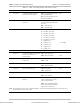
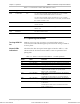
Table 2-1 ASMi-31 Internal Jumpers and Switches (Cont.)
Item Jumper Description Values Default Setting
Section 7 Controls the DTR to DSR
transfer
ON – Indicates onl
y
that the
local unit is
p
owered u
p
. It
does not indicate the status of
the communication channel or
o
p
erational status of the remote
site
OFF – Indicates that the DSR of
the local unit follows the DTR
signal of the remote unit
DSR
Section 8 Controls the ASMi-31
o
p
erational status – slave or
master
ON – Slave
OFF – Master
Slave
Closing the ASMi-31 Case
After completing the internal settings, close the unit case.
➤
➤ ➤
➤ To close the ASMi-31 case:
1. Replace the upper half of the unit and press firmly until the plastic tabs
fit into the tab housing.
2. Insert the original cover screws in their positions and tighten carefully.
Do not use excessive torque.
Connecting the
Interfaces
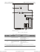
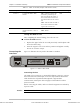
Figure 2-2 illustrates the rear panel of the ASMi-31 modem.
~230V 0.1A T 250V
DTE
LINE
GND
245
Figure 2-2 ASMi-31 Rear Panel
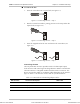
Connecting the Line
The ASMi-31 line connector is a terminal block/RJ-45 connector. Connect
the transmission line (twisted pair) to the two clips marked LINE and the
cable shield to the clip marked GND (optional). High rate data
communication twisted pair cable is highly recommended in order to
prevent crosstalk.
Before connecting the cables, make sure that the equipment is earthed by
its power cable.
Caution
Insert the GND lead first.
Order from: Cutter Networks
Ph:727-398-5252/Fax:727-397-9610
www.bestdatasource.com