
Specifications


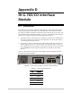


Appendix D IR-G.703/CO Interface Module Installation and Operation Manual
D-2 Selecting the IR-G.703/CO Timing ASMi-31 Ver. 3.0
For the G.703 codirectional interface, byte synchronization is not kept end-to-
end. A violation bit is inserted every eight bits, but it does not appear in the same
location at the remote end.
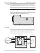
D.2 Selecting the IR-G.703/CO Timing
The IR-G.703/CO interface module can operate with EXT or INT/RCV timing to
match the clock reference of the ASMi-31 modem. The clock selection is made via
the JP1 jumper located on the module board (see
Figure D-2
).
JP1
INT/RCV
EXT
Figure D-2. JP1 Location on the IR-G.703/CO Board
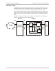
EXT Timing
The EXT clock is used in applications, where the system timing is provided by the
G.703 network. The IR-G.703/CO module has an internal buffer to compensate
for the phase delay introduced to the system by the line delay between the two
modems. The buffer is an 8-bit FIFO connected as shown in
Figure D-3
.
You must configure the IR-G.703/CO module to the EXT clock if the ASMi-31
modem is also set to the external timing.
Timing Source
TX Data
TX
TX
RX
RX
RX Data
G.703
Codirectional
64 kbps Network
FIFO
EXT Clock Mode RCV Clock Mode
Clock In
Clock
Out
Modem A Modem B
Clock
Recovery
Data
Data
CLK
Clock
Recovery
FIFO
IR-G.703 Module
Clock
Recovery
Figure D-3. IR-G.703/CO EXT Timing
Note