
Specifications

ASMi-31 Ver. 3.0 V.24, V.35, X.21 and RS-530 DTE Interface Connectors A-1
Appendix A
Pinouts
A.1 V.24, V.35, X.21 and RS-530 DTE Interface
Connectors
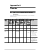
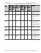
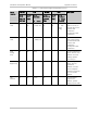
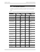
Table A-1
lists the pin assignments of the V.24/RS-232, V.35, X.21 and RS-530
interface connectors.
Table A-1. DTE Interface Signal Assignments
V.24 V.35 RS-530 X.21 Description Signal
Function
DB-25
Stand-
alone and
Card Cage
DB-25
Card
Cage
34-Pin
Standalone
Pin Circuit
DB-25
Standalone
and Card
Cage
DB-25
Card
Cage
DB-15
Standalone
Pin Circuit
(Function)
Protective
Ground
1 1 A Frame 101 1 1 1
(Shield)
Chassis Ground. It may
be isolated from Signal
Ground.
Signal
Ground
7 7 B Signal 102
7
7 8
(GND)
Common signal and DC
power supply ground.
Transmitted
Data
2 9
11
P TD(A) 103
S TD(B) 103
2
14
2
14
2
9
(Transmit)
Serial digital data from
DTE. In sync
applications, the data
translations must
occur on the rising
edge of the transmit
clock.
Received
Data
3 12
13
R RD(A) 104
T RD(B) 104
3
16
3
16
4
11
(Receive)
Serial output from the
modem receiver. In
sync applications, the
data translations occur
on the rising edge of
the clock.