
Specifications

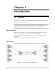


Chapter 1 Introduction Installation and Operation Manual
1-4 Functional Description Optimux-106 Ver. 6.1
Table
1-1
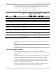
provides information on the characteristics of the optical subsystem,
including the maximum range over typical fiber optic cable. The maximum range
values given in the table below assume a margin of 3 dB.
Table
1-1 Fiber Optic Interface Characteristics
Wavelength
[nm]
Fiber Type
[μm]
Transmitter
Type
Typical
Output
Power
[dBm]
Receiver
Sensitivity
[dBm]
Typical Max.
Range
[km miles]
Connector
Type
850 62.5/125 multimode Laser (VCSEL) -6 -34* 4.5 2.8 ST, SC, FC/PC
1310 9/125 single mode Laser -12 -34 47 29.2 ST, SC, FC/PC
1310 62.5/125 multimode LED -18 -32 7 4.3 ST, SC
1310 9/125 single mode Laser
[long haul]
-2 -34 72 44.7 ST, SC, FC/PC
1310
Transmit/Receive
9/125 single mode
Single fiber
Laser [SF3] -12 -27 20 12.4 SC/APC only
1310/1550
Transmit/Receive
9/125 single mode
Single fiber
Laser WDM
[SF1]
-12 -34 47 29.2 SC
1550/1310
Transmit/Receive
9/125 single mode
Single fiber
Laser WDM
[SF2]
-12 -34 47 29.2 SC
1550 9/125 single mode Laser -12 -34 76
47.2
ST, SC, FC/PC
1550 9/125 single mode Laser
[long haul]
-2 -34 120
74.5
ST, SC, FC/PC
* The Receiver Sensitivity for units with the Ethernet port is 32 dBm.
All fiber optic interface options offer high performance and have a wide dynamic
range.
The SF3 option uses an SC/APC connector. The FO cable connected to it must
therefore be of the same type.
Uplink Redundancy Option
Optimux-106 can be ordered with one or two link interface options. Each
interface operates independently, and can be ordered from the link options listed
above.
In the uplink redundancy option, Optimux-106 supports fully automatic switching
between the main and the backup link. The main link has priority, therefore
normally it is selected for use, and the backup link is disabled. In case a failure
occurs on the main link, Optimux-106 automatically switches to the backup link
and continues providing normal service. After the main link returns to normal
operation, it is automatically reselected.
Each link interface has its own set of indicators that display the current state of
the link. AIS alarm does not appear for the non-active optical link.