
Specifications

Chapter 2 Installation and Setup Installation and Operation Manual
2-4 Connecting the Interfaces Optimux-106 Ver. 6.1
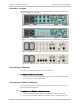
Connector Location
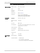
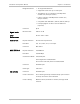
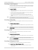
The following figures show the typical Optimux-106 rear panels. Connector pin
allocations appear in
Appendix A
.
Figure
2-1 Plastic Enclosure, Ethernet User Port and Unbalanced T1 Tributaries
Figure
2-2. Plastic Enclosure, Ethernet User Port and Balanced T1 Tributaries
Figure
2-3 Metal Enclosure, Ethernet User Port and Unbalanced T1 Tributaries
Figure
2-4. Metal Enclosure, Ethernet User Port and Balanced T1 Tributaries
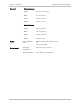
Connecting to Channels
The tributary interfaces include four RJ-45 connectors.
³ To connect the tributary connectors:
• Connect each of the tributary cables to the RJ-45 connector(s) designated
CH1, CH2, CH3, or CH4, respectively.
Connecting to Ethernet Network
The User Ethernet port includes one RJ-45 connector used to connect to the
Ethernet network equipment.
³ To connect to the Ethernet network equipment:
1. Connect the RJ-45 Ethernet cable to the Ethernet network equipment.
2. Connect the other side of the RJ-45 Ethernet cable to the USER-ETH port.