
Specifications

Installation and Operation Manual Chapter 2 Installation and Setup
Optimux-106 Ver. 6.1 Connecting the Interfaces 2-5
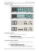
Connecting to Uplink Equipment
Connect the uplink (A and B) using two groups of connectors, one for Link A and
the other for optional Link B. Use ST, SC, FC/PC or SC/APC connectors as relevant.
For each uplink interface (A and B), connect as follows:
³ To connect the uplink:
1. Clean the optical connectors using an approved solvent, and dry thoroughly
using optical tissue.
2. Connect to the two optical connectors designated TX (transmit output) and
RX (receive input) of the appropriate interface.
3. Verify the correct connection of the transmit and receive cables to the
corresponding connectors. Avoid sharp bends and twisting of the fiber-optic
cables.
For the WDM option, connect only one fiber optic cable per link.
Connecting to Alarm Relay
This connector connects the changeover contacts of the major and minor alarm
relays.
³ To connect the alarm connector:
• Connect the alarm relays via the ALARM connector (RJ-45) located on the rear
panel.
Connection of the alarm port is made using a special cable, RJ45 to DB9/female,
CBL-RJ45-DB9/F.
Connecting to DCE
This connector connects the RS-232 serial port of the station to the DCE
interface on the board.
³ To connect the control connector:
• Connect the control cable to the mini USB connector at the rear panel and to
the DCE device.
Connection of the control port is made using a special cable, Mini-USB to
DB9/female, CBL-MUSB-DB9F
Connecting to Management Station
The Optimux-106 user interface terminates in an 8-pin RJ-45 connector.
³ To connect the user Ethernet Management Port:
• Connect the management station to the MNG-ETH connection using a
UTP-CAT5 cable.
Note
Note
Note