
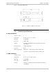
Specifications


Chapter 2 Installation and Setup Installation and Operation Manual
2-2 Inserting the MiRIC-E1, MiRIC-T1 MiRIC-E1, MiRIC-T1 Ver. 1.5
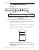
INT
RCV Un-FRM
FRM
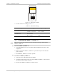
Figure 2-1. DIP Switch Location
2. Set DIP switches according to
Table 2-1.
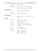
Table 2-1. DIP Switch Settings
Switch Identity Possible Settings Factory Setting
Framing FRM – Framed
Un-FRM – Unframed
T1 – Un-FRM
E1 – Un-FRM
Transmit clock INT – Internal
RCV – Receive
RCV
2.5 Inserting the MiRIC-E1, MiRIC-T1
There is no need to power down the host unit when inserting or extracting the
MiRIC-E1, MiRIC-T1.
To insert a MiRIC-E1, MiRIC-T1
1. Insert the MiRIC device into a free SFP (MSA-compatible) socket of the host
equipment.
2. Make sure that the MiRIC-E1, MiRIC-T1 is pressed firmly into the MSA SFP
port connector.
3. The MiRIC-E1, MiRIC-T1 is ready to operate.
To remove a MiRIC-E1, MiRIC-T1
1. Disconnect any cables attached to the MiRIC.
1. Push the release button on the front of the MiRIC-E1, MiRIC-T1. This extracts
the device from the edge connector.
2. Remove the MiRIC-E1, MiRIC-T1 from the socket.
Note