RADview-SC/TDMoIP Network Management System Service Center for TDMoIP Applications IPmux-8/16 © 1994–2005 RAD Data Communications Publication 11/05
Contents Chapter 1. Introduction 1.1 The IPmux-8/16 Device .................................................................................... 1-1 1.2 Managing IPmux-8/16 with RADview SC/TDMoIP............................................. 1-1 Overview of RADview FCAPS Model .......................................................................1-2 Overview of IPmux-8/16 Management Functions .....................................................1-2 Chapter 2. Installation and Setup 2.
Table of Contents Application ..............................................................................................................4-1 Guidelines for Configuring IPmux Units....................................................................4-2 4.2 Configuring IPmux-11 Units .............................................................................. 4-4 Configuring the IP Parameters ..................................................................................
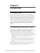
Chapter 1 Introduction 1.1 The IPmux-8/16 Device IPmux-8 and IPmux-16 (referred to as IPmux-8/16) are modular TDMoIP gateways. IPmux-8/16 modules enable TDM circuits to be extended over Packet Switched Networks (PSN) . The devices convert the data stream coming from the TDM ports into configurable-sized Ethernet frames that are transported over the Ethernet port and vice versa.
IPmux-8/16 User’s Manual Chapter 1 Introduction Overview of RADview FCAPS Model RADview provides a complete solution for monitoring and controlling IPmux. The RADview solutions conform to ITU-T Telecommunication Management Network (TMN) recommendations for SNMP management systems, known as the FCAPS model: • Fault management – detects and correlates fault in network devices, isolates faults and initiates recovery actions.
IPmux-8/16 User’s Manual Chapter 1 Introduction Table 1-1. Management Functions (Cont.
Chapter 1 Introduction 1-4 Managing IPmux-8/16 with RADview SC/TDMoIP IPmux-8/16 User’s Manual
Chapter 2 Installation and Setup This chapter describes how to set up IPmux-8/16 for management and connect it to the management station, and includes the following sections: • Configuring IPmux-8/16 for Management • Connecting IPmux-8/16 to the Management Station 2.1 Configuring IPmux-8/16 for Management To remotely administer IPmux via a Network Management Station (NMS), it is necessary to first configure some basic IPmux parameters via an ASCII terminal session to the IPmux Control Port.
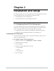
IPmux-8/16 User’s Manual Chapter 2 Installation and Setup Configuration>System>Host IP 1. IP address ... (192.168.10.1) 2. IP mask ... (255.255.255.0) 3. Default gateway ... (0.0.0.0) 4. DHCP (Disable) 5. DHCP Status > > Please select item <1 to 5> ESC-prev.menu; !-main menu; &-exit 1 Mngr/s Figure 2-1. Configuring the Host IP Parameters for IPmux-8/16 Configuring the Manager List To configure the Manager List: 1.
IPmux-8/16 User’s Manual Chapter 2 Installation and Setup 2.2 Connecting IPmux-8/16 to the Management Station IPmux-8/16 can be managed by a Network Management Station (NMS) that is located on the LAN (hub or switch) connected to the one of the unit’s Ethernet ports. To connect IPmux-8/16 to the network management station: 1. Connect a network management station to the LAN (hub or switch). 2. Connect one of IPmux’s Ethernet ports to the LAN.
Chapter 2 Installation and Setup 2-4 Connecting IPmux-8/16 to the Management Station IPmux-8/16 User’s Manual
Chapter 3 Configuration Management This chapter describes how to configure IPmux-8/16 on all levels: system and port, and contains the following sections: • Using the RADview User Interface • Configuring General Parameters • Configuring IPmux-8/16 Ports at the Physical Layer • Assigning Timeslots to Bundles • Managing Bundle Connections • Additional Tasks. 3.
Chapter 3 Configuration Management IPmux-8/16 User’s Manual By selecting a row, you can manipulate the selected system or port. When selected, a light blue frame is displayed around the selected window, and the selected row is colored with dark gray. Only one entry can be selected at a time. Figure 3-1. Element Manager – IPmux-8 Figure 3-2.
IPmux-8/16 User’s Manual Chapter 3 Configuration Management Figure 3-3. Element Manager - IPmux-16 Channelized T3 Selecting the Device or a Port IPmux-8/16 is managed by selecting one of its two levels of objects and then selecting the desired function from the menus. These are two IPmux-8/16 user interface object levels: • System (whole device) – This level contains all the parameters and functions common to the whole device.
IPmux-8/16 User’s Manual Chapter 3 Configuration Management System Level Menu Options The element manager allows you to configure the device parameters. To configure an IPmux via the element manager: • Select the node in the Service Center map and from the Configuration menu, select Element Manager... The Element Manager dialog box (Figure 3-1, Figure 3-2, Figure 3-3) appears allowing you to configure any of the elements listed. Table 3-2.
IPmux-8/16 User’s Manual Chapter 3 Configuration Management Tasks - Statistics Dialog Box and Parameter Location Path Setting polling interval Polling Interval dialog box See Setting Polling Interval Statistics Polling Interval… Viewing Bundle statistics Bundle ConnectionTable See Viewing Bundle Statistics Statistics Bundle Statistics… Options Dialog Box and Parameter Location Path Lists Host Interfaces IP Host Interfaces IP List dialog box See Host Interface IP List Options Host Interfaces
IPmux-8/16 User’s Manual Chapter 3 Configuration Management Table 3-3. Port Level Management Options (Cont.
IPmux-8/16 User’s Manual Chapter 3 Configuration Management Configuring System Parameters To set system parameters for the selected IPmux device: 1. Configuration > System Parameters... The System Parameters dialog box appears (Figure 3-4). 2. Enter the required settings. 3. Click to implement the changes. Figure 3-4. System Parameters Dialog Box Table 3-4.
IPmux-8/16 User’s Manual Chapter 3 Configuration Management Table 3-4. System Parameters (Cont.
IPmux-8/16 User’s Manual Chapter 3 Configuration Management Figure 3-5. System Information Dialog Box Maintaining the Manager List The Manager List command enables you to establish the actual link between the selected IPmux device and the manager. Note You can define a maximum of ten managers for each host. To display the manager list: • Options > Manager List... The Manager List appears.
IPmux-8/16 User’s Manual Chapter 3 Configuration Management Figure 3-6. Manager List Table 3-5. Manager List Parameters Parameter Possible Values/Remarks Manager IP Address IP address of the Network Management System Host Name LAN1, LAN2, OOB (out of band) Next Hop IP Address IP address of next Hop Mask Traps Indicates whether or not traps are masked by the system Yes, No Access Ports Defines from which port or ports this manager can configure the device: Port1..
IPmux-8/16 User’s Manual Chapter 3 Configuration Management Figure 3-7. Add Manager Dialog Box Table 3-6. Add Manager Parameters Parameter Possible Values / Remarks Host Name LAN1, LAN2, OOB (out of band) Manager IP Address IP address of the selected entry Next Hop IP Address For Agent version ≥ 2.0 Access Ports Defines from which port or ports this manager can configure the device: Port1..Port4 All All Users VLAN Tagging Yes, No ID 1 ..4094 Priority 0..
IPmux-8/16 User’s Manual Chapter 3 Configuration Management To change an entry in the manager list: 1. Select an entry in the Manager List and click The Change Manager dialog box appears (Figure 3-8). 2. Enter the required settings. 3. Click to implement the changes. Figure 3-8. Change Manager Dialog Box To remove an entry from the Manager List: 1. Select a row from the Manager List and click . A message appears warning about possible disconnection of the Agent. 2.
IPmux-8/16 User’s Manual Chapter 3 Configuration Management Figure 3-10. Host Interface IP List Table 3-7. Host Interface IP Parameters Parameter Possible Values / Remarks Host Name LAN1, LAN2, OOB (out of band) Host Interface IP IP address of the Host Interface Host IP Mask IP address of the Host MAsk Default Next Hop IP address of next Hop Default VLAN Tagging Yes, No VLAN ID 1 to 4094 VLAN Priority 0 to 7 To add an entry in the Host Interface IP List: 1.
IPmux-8/16 User’s Manual Chapter 3 Configuration Management Figure 3-11. Add Host Interface IP Note You cannot add an entry in the Host Interface IP List if all 3 Hosts (ETH1, ETH2, and Control (OOB)) exist in the Host Interface IP List, or if one ETH slot exists in the device, and this ETH and the Control (OOB) Hosts exist in the Host Interface IP List. To remove an entry from the Host Interface IP List: 1.
IPmux-8/16 User’s Manual Chapter 3 Configuration Management Configuring the VLAN Table of the Ethernet Switch The VLAN Table > Bridge 1/2 command enables you to establish virtual LANs (VLANs) to segment your network into multiple smaller networks. You can use VLANs to reduce traffic on each network segment and to increase security. To view the VLAN table: 1. Configuration > VLAN Table > Bridge 1... (or Bridge 2….) The Bridge 1 (or 2) VLAN Table dialog box appears. Figure 3-12.
IPmux-8/16 User’s Manual Chapter 3 Configuration Management You have the following options: • Add a VLAN • Change a VLAN • Remove a VLAN To add a VLAN to the VLAN Table: 1. Click Add. The Add VLAN dialog box appears. 2. Configure the desired parameters. 3. Click Apply. The VLAN, if valid, is added to the VLAN Table. 4. Click Close. The Add VLAN dialog box is closed and the new entries are added to the end of the list in the VLAN Table Dialog Box.
IPmux-8/16 User’s Manual Chapter 3 Configuration Management Figure 3-14. VLAN Table – Change VLAN Dialog Box To remove a VLAN from the VLAN Table: 1. Select the row of the VLAN to be removed. 2. Click Remove. The VLAN is removed from the VLAN Table. 3.3 Configuring IPmux-8/16 Ports at the Physical Layer At port level, you can configure parameters for: • Ethernet ports • E1/T1 ports • E3/T3 ports. Configuring Ethernet Parameters To set configuration parameters for the Ethernet interface: 1.
Chapter 3 Configuration Management IPmux-8/16 User’s Manual Figure 3-15. Ethernet Interface Parameters Dialog Box Table 3-9. Ethernet Interface Parameters Parameter Possible Values / Remarks Slot 1, 2 Note: This does not appear for OOB.
IPmux-8/16 User’s Manual Chapter 3 Configuration Management Table 3-9. Ethernet Interface Parameters (Cont.
IPmux-8/16 User’s Manual Chapter 3 Configuration Management Configuring E1/T1 Parameters To display or configure E1/T1 parameters: 1. Click an E1/T1 port. 2. Configuration > Parameters... The E1/T1 Parameters dialog box appears. Figure 3-16.
IPmux-8/16 User’s Manual Chapter 3 Configuration Management Figure 3-17. T1 Parameters Dialog Box Table 3-10. E1/T1 Parameters Parameter Possible Values / Remarks Slot 3, 4 Port CH1 to CH8 Type E1, T1 Admin.
IPmux-8/16 User’s Manual Chapter 3 Configuration Management Table 3-10. E1/T1 Parameters (Cont.) Parameter Possible Values / Remarks Line Type Line type affects the number of bits per second that the link can reasonably carry. It also affects the interpretation of the port performance statistics. For E1 ports: Framed (G.704), Framed-CRC, Framed-MF, Framed-CRC-MF Unframed (G.
IPmux-8/16 User’s Manual Chapter 3 Configuration Management Table 3-10. E1/T1 Parameters (Cont.
IPmux-8/16 User’s Manual Chapter 3 Configuration Management Configuring Internal T1 Parameters To display or configure Internal T1 port parameters: 1. Click an Internal T1 port. 2. Configuration > Parameters... The T1 Parameters dialog box appears. Figure 3-18. Internal T1 Parameters Dialog Box Table 3-11. Internal T1 Parameters Parameter Possible Values / Remarks Slot 3, 4 Port CH1..
IPmux-8/16 User’s Manual Chapter 3 Configuration Management Configuring E3/T3 Parameters To display or configure E3/T3 parameters: 1. Click an E3/T3 port. 2. Configuration > Parameters... The E3/T3 Parameters dialog box appears. Figure 3-19. E3/T3 Parameters Dialog Box Table 3-12.
IPmux-8/16 User’s Manual Chapter 3 Configuration Management Configuring CT3 Parameters To display or configure CT3 parameters: 1. Click a CT3 port. 2. Configuration > Parameters... The CT3 Parameters dialog box appears. Figure 3-20. CT3 Parameters Dialog Box Table 3-13.
IPmux-8/16 User’s Manual Chapter 3 Configuration Management Configuring CT3 Clocks To display or configure CT3 clock parameters: 1. Click a CT3 port. 2. Configuration > Clocks... The Clocks Parameters dialog box appears. Figure 3-21.
IPmux-8/16 User’s Manual Chapter 3 Configuration Management Table 3-14. Clocks Parameters Parameter Possible Values / Remarks Slot 3, 4 Port Channelized T3 Type CT3 T3 Tx. Clock Source The source of Transmit Clock. LBT: the recovered receive clock is used as the transmit clock Internal: a local clock source is used or that an external clock is attached to the box containing the interface Internal 1..28 Tx. Clock Source The source of Transmit Clock.
IPmux-8/16 User’s Manual Chapter 3 Configuration Management 3.4 Assigning Timeslots to Bundles Note Bundle is not relevant for unframed Line Type. To view bundles for an E1/T1 port: 1. Click an E1/T1 port. 2. Configuration > Bundles... The Bundle screen appears. Figure 3-22. Bundles – Port Level Bundles are groups of timeslots.
Chapter 3 Configuration Management IPmux-8/16 User’s Manual Table 3-15. Bundle Parameters – Port Level Parameter Possible Values / Remarks Slot Slot Port Port Type E1, T1 Bundle No.
IPmux-8/16 User’s Manual Chapter 3 Configuration Management Creating Bundle Connections For information on creating and managing bundle connections using the Service Center map, refer to chapter 7 of the RADview SC/TDMoIP System Manual. Removing Bundle Connections For information on removing bundle connections using the Service Center map, refer to chapter 7 of the RADview SC/TDMoIP System Manual.
Chapter 3 Configuration Management IPmux-8/16 User’s Manual Table 3-16. Bundle Connection Table Parameters (Cont.) Parameter Possible Values/Remarks Dest. Bundle Bundle number in the destination IPmux device For E1: 1 to 496 For T1: 1 to 384 Jitter Buffer (tens of µsec Depth of the jitter buffer (elastic buffer per link whose size is configurable in units of 10 micro seconds (µs). T1: 0..3.. 2400 (0 - 24 ms) E1: 0..3..3200 (0 - 32 ms) T3/E3: 0..3..
IPmux-8/16 User’s Manual Chapter 3 Configuration Management Figure 3-24. Remove Bundle Connection 3. Click to confirm remove. 3.6 Additional Tasks Displaying Ethernet Interface Information To display information about an Ethernet interface 1. Click an Ethernet port. 2. Configuration > Interface Info... The Interface Information dialog box appears. Figure 3-25. LAN Interface Information Note The field Slot does not appear for OOB (out-of-band).
IPmux-8/16 User’s Manual Chapter 3 Configuration Management Table 3-17. Ethernet Interface Parameters Parameter Possible Values / Remarks Slot 1, 2 Note: This does not appear for OOB.
IPmux-8/16 User’s Manual Chapter 3 Configuration Management Resetting IPmux-8/16 to the Default Configuration To set the selected IPmux to the Default Configuration: 1. Configuration > System Commands > Default Configuration. The following message appears: RESETTING AGENT CONFIGURATION. Current configuration will be lost. 2. Click to confirm reset of the default configuration. The default configuration replaces the current configuration.
Chapter 3 Configuration Management 3-36 Additional Tasks IPmux-8/16 User’s Manual
Chapter 4 Configuring Typical Applications This chapter provides detailed instructions for setting up a typical application using two IPmux-11 units opposite an IPmux-16 unit, and contains the following sections: • Overview • Configuring IPmux-11 Units • Configuring IPmux-16 • Connecting IPmux to the Management Station • Configuration Sequence • Creating Circuits 4.
IPmux-8/16 User’s Manual Chapter 4 Configuring Typical Applications Guidelines for Configuring IPmux Units Certain guidelines are relevant to this application. In general, there are four basic configuration steps (described below) that need to be followed when deploying any IPmux unit. 1. IP Configuration – Setting the device host IP address and the manager IP address.
IPmux-8/16 User’s Manual Chapter 4 Configuring Typical Applications Configuration Summary Table Table 4-2. Configuration Summary Device E1 Parameters IP Parameters Bundle Creation Bundle Connection IPmux-11 (A) • Transmit clock source: adaptive Host IP address: 10.10.10.126 Bundle No. 1 Timeslots in bundle: 1–10 IPmux-16 Ethernet port 1 Host IP address: 40.40.40.111 Bundle No. 1 Timeslots in bundle: 1–10 IPmux-16 Ethernet port 2 • Out-of-band host IP address: 40.40.40.102 Bundle No.
Chapter 4 Configuring Typical Applications IPmux-8/16 User’s Manual 4.2 Configuring IPmux-11 Units This section explains how to configure IPmux-11 units. The configuration procedure is similar for both units. Configuring the IP Parameters To configure the host IP parameters: 1. Display the Host IP menu (Configuration > System > Host IP), and configure the IP address and mask of the host. 10.10.10.126 for IPmux-11 (A) host 40.40.40.111 for IPmux-11 (B) host. 2. Save the changes.
IPmux-8/16 User’s Manual Chapter 4 Configuring Typical Applications 4.4 Connecting IPmux to the Management Station IPmux can be managed by a Network Management Station (NMS) that is located on the LAN (hub or switch) connected to the one of the unit’s Ethernet ports. To connect IPmux to the Network Management Station: 1. Connect a Network Management Station to the LAN (hub or switch). 2. Connect one of the IPmux’s Ethernet ports to the LAN. 4.
Chapter 4 Configuring Typical Applications IPmux-8/16 User’s Manual 4.6 Creating Circuits In the Service Center application, circuits can be created for Mesh and Normal Services. This section demonstrates creating circuits as a Mesh Service. For more information, see the RV-SC/TDMoIP System Manual. Creating Mesh Service Circuit Figure 4-2.
IPmux-8/16 User’s Manual Chapter 4 Configuring Typical Applications Defining E1 Parameters To configure E1 parameters for the source IPmux-16: 1. Double click on the desired IPmux-16 source (40.40.40.102) in the Mesh Services Map (Figure 4-2). The Element Manager appears. Figure 4-3. IPmux-16 Element Manager 2. Select CH1. 3. From the Configuration menu, select Parameters... The Interface Parameters dialog box appears (Figure 4-4). 4.
IPmux-8/16 User’s Manual Chapter 4 Configuring Typical Applications Figure 4-4. IPmux-16 E1 Interface Parameters To configure E1 parameters for the destination IPmux-11: 1. Double click on the desired IPmux-11 destination (10.10.10.126) in the Mesh Services Map (Figure 4-2). The Element Manager appears. Figure 4-5. IPmux-11 Element Manager 2. Select CH1.
IPmux-8/16 User’s Manual Chapter 4 Configuring Typical Applications 3. From the Configuration menu, select Parameters... The Interface Parameters dialog box appears (Figure 4-6). 4. Select the following parameters: Transmit Clock Source = Adaptive 5. Click . Figure 4-6. IPmux-11 E1 Interface Parameters Creating Circuit To create a circuit between IPmux-16 (40.40.40.102) and IPmux-11 (10.10.10.126): 1. On the Services Map, select the source for the circuit. In this example it is the IPmux-16 (40.40.
Chapter 4 Configuring Typical Applications IPmux-8/16 User’s Manual Figure 4-7. Manual Circuit Dialog Box – General Parameters Tab 3. Click on the General Tab (Figure 4-7) and configure the following parameters: Connection Type = E1 Connection Bandwidth = 10xTS 4. Click on the Primary Circuit Tab (Figure 4-7) and configure the following parameters: Line Type = Framed (G.
IPmux-8/16 User’s Manual Chapter 4 Configuring Typical Applications Figure 4-8. Manual Circuit Dialog Box – Primary Circuit Tab 5. If the devices are on a network segment that uses VLANs, click on the EP Param Tab (Figure 4-9) and configure the following parameters: VLAN Tagging = Enabled (Checked) VLAN ID = 111 VLAN Priority = 2 Note Use the vertical scroll bar on the right side of the dialog box to scroll the window and display fields that are off the page.
Chapter 4 Configuring Typical Applications 4-12 Creating Circuits IPmux-8/16 User’s Manual
IPmux-8/16 User’s Manual Chapter 4 Configuring Typical Applications Figure 4-9.
IPmux-8/16 User’s Manual Chapter 4 Configuring Typical Applications Save Circuit Parameter Settings To save parameter settings: 1. In the Manual Circuit Dialog Box, click . A message appears asking you if you want to create another circuit. Figure 4-10. Create Another Circuit Dialog 2. Click . The circuit is created and appears on the Mesh Services Map. 3.
IPmux-8/16 User’s Manual Chapter 4 Configuring Typical Applications Displaying Circuit Parameters Using the Services Map, you can display the circuit parameters of a link to verify that the parameters are correct. To display circuit parameters: 1. Click on a link in the Services Map (Figure 4-11). 2. Right click and select Circuit List… The Circuit List appears. Figure 4-12. Circuit List 3. Click The Manual Circuit Parameters dialog box appears. 4. Verify that the parameters are correct.
Chapter 4 Configuring Typical Applications 4-16 Creating Circuits IPmux-8/16 User’s Manual
Chapter 5 Security Management This chapter discusses how to manage IPmux-8/16 security, and includes the following section: • Enabling or Disabling Telnet Access 5.1 Enabling or Disabling Telnet Access The Access command allows you to enable Telnet access. To enable Telnet access: 1. Options > Access… The Access dialog box appears (Figure 5-1). 2. Configure Telnet Access and click . Figure 5-1. Access Dialog Box Table 5-1.
Chapter 5 Security Management 5-2 Enabling or Disabling Telnet Access IPmux-8/16 User’s Manual
Chapter 6 Performance Management This chapter discusses how to monitor IPmux-8/16 performance, and includes the following sections: • Setting the Polling Interval • Viewing Bundle Statistics • Viewing Bundle Current Statistics • Viewing Bundle Intervals Statistics • Viewing Ethernet Port Statistics • Viewing E1/T1, E3/T3 Port Statistics • Viewing CT3 Port Statistics. 6.1 Setting the Polling Interval To configure the polling interval: 1.
Chapter 6 Performance Management IPmux-8/16 User’s Manual Figure 6-2. Bundle Connection Table – Statistics Table 6-1. Bundle Connection Parameters – Statistics Parameter Remarks Slot No. Slot nunber 1 to 4 Channel No. Channel to be configured 1 to 8 Bundle No. For E1: 1 to 496 For T1: 1 to 384 Bundle Name Bundle name for selected channel. Admin Status Connected, Disconnected Oper. Status Connected, Disabled, Remote Fail, Local Fail Dest.
IPmux-8/16 User’s Manual Chapter 6 Performance Management 6.3 Viewing Bundle Current Statistics To view the Bundle Current Table: • From the Bundle Connection Statistics table (Figure 6-2), click . The Bundle Current statistics dialog box appears. Figure 6-3.
Chapter 6 Performance Management IPmux-8/16 User’s Manual Table 6-2. Bundle Current Statistics Parameters Parameter Remarks Bundle No. For E1: 1 to 496 For T1: 1 to 384 Bundle Name Bundle name for selected channel Time Elapsed (sec) Amount of time that has passed since the beginning of the current 15-minute interval 0..899 Sequence Errors Number of times frames were dropped because frames were received from the network with SN fields not equal to the last SN + 1 (or 2).
IPmux-8/16 User’s Manual Chapter 6 Performance Management Figure 6-4. Bundle Intervals Statistics The Bundle Intervals Data parameters are the same as the Bundle Current Data Parameters (Table 6-2) with the addition of information regarding Interval No. and its duration.
IPmux-8/16 User’s Manual Chapter 6 Performance Management 6.5 Viewing Ethernet Port Statistics To view interface statistics for the Ethernet interface: 1. Click the Ethernet interface. 2. From the Statistics menu, select Interface Statistics ... The Interface Statistics dialog box appears (Figure 6-5). Figure 6-5. Interface Statistics – Ethernet Table 6-3.
IPmux-8/16 User’s Manual Chapter 6 Performance Management Table 6-3. Interface Statistics Parameters – Ethernet (Cont.) Parameter Remarks Single Collision Frames Counter of successfully transmitted frames for which transmission is inhibited by exactly one collision. Valid only in half duplex mode. Multiple Collision Frames Counter of successfully transmitted frames for which transmission is inhibited by more than one collision. Valid only in half duplex mode.
IPmux-8/16 User’s Manual Chapter 6 Performance Management 6.6 Viewing E1/T1, E3/T3 Port Statistics You can view a selected 15-minute interval or cumulative totals of the data from the previous 24 hours. Current statistics for a specific E1/T1 port can be viewed in list or graph form. Viewing E1/T1, E3/T3 Port Current Statistics To view the Current Statistics: • Statistics > Current… The Port Current Statistics dialog box appears (Figure 6-6).
IPmux-8/16 User’s Manual Chapter 6 Performance Management Table 6-4. Current Data Parameters – E1/T1 Parameter Remarks Slot 3, 4 Port Port number of the interface CH1..CH8 Type E1, T1 Current Data Each parameter displays the number of seconds of that particular type of error encountered by the E1/T1 interface during the current 15-minute interval Time Elapsed (sec) Amount of time that has passed since the beginning of the current 15-minute interval LOS 0..899 Loss of Signal failure Sync.
IPmux-8/16 User’s Manual Chapter 6 Performance Management Table 6-4. Current Data Parameters – E1/T1 (Cont.) Parameter Remarks SES Severely Errored Seconds 320 or more CRC error events, one or more SEF (OOF), or AIS. OOF defect is the occurrence of framing bits error UAS Unavailable Seconds Number of seconds that the interface is unavailable. The system is unavailable after 10 continuous SES.
IPmux-8/16 User’s Manual Chapter 6 Performance Management Table 6-5. Current Data Parameters – E3/T3 (Cont.) Parameter Possible Values / Remarks LOS Loss of Signal failure Sync. LED turns off during LOS For T3: Upon observing 192 contiguous pulse positions with no pulse of either positive or negative polarity. (Signal is more than 30dB below nominal amplitude). For E3: Upon observing 255 contiguous pulse positions with no pulse of either positive or negative polarity.
IPmux-8/16 User’s Manual Chapter 6 Performance Management Viewing E1/T1, E3/T3 Port Intervals Statistics If more than one measurement interval has passed since the IPmux startup or reset, you can view a selected 15-minute interval or cumulative totals of the data from the previous 24 hours in a graph or a table. Statistics from previous intervals for a specific E1/T1 or E3/T3 port can be viewed in list or graph form. To view a list of statistics from previous intervals: 1. Click an E1/T1 or E3/T3 port: 2.
IPmux-8/16 User’s Manual Chapter 6 Performance Management The Intervals Data - E1/T1 parameters are the same as the Current Data Parameters (Table 6-4) with the addition of information regarding Interval No., its duration and the following parameters: Table 6-6.
IPmux-8/16 User’s Manual Chapter 6 Performance Management 6.7 Viewing CT3 Port Statistics You can view a selected 15-minute interval or cumulative totals of the data from the previous 24 hours. Viewing CT3 Port Current Statistics To view the Current Statistics: 1. Select a CT3 port. 2. Statistics > Current… The channelized T3 Current Statistics dialog box appears. Figure 6-8.
IPmux-8/16 User’s Manual Chapter 6 Performance Management Table 6-7. Channelized T3 Current Statistics Parameters Parameter Remarks Slot 3, 4 Port Channelized T3 Time Elapsed (sec) Amount of time that has passed since the beginning of the current 15-minute interval LOS 0..899 Loss of Signal failure Sync. LED turns off during LOS For T1: Upon observing 192 contiguous pulse positions with no pulse of either positive or negative polarity. (Signal is more than 30dB below nominal amplitude).
Chapter 6 Performance Management IPmux-8/16 User’s Manual Viewing CT3 Port Intervals Statistics If more than one measurement interval has passed since the IPmux startup or reset, you can view a selected 15-minute interval or cumulative totals of the data from the previous 24 hours in a graph or a table. To view a list of statistics from previous intervals: 1. Click a CT3 port: 2. Statistics > Intervals… The channelized T3 Intervals Statistics dialog box appears. Figure 6-9.
Chapter 7 Fault Management This chapter describes how to manage IPmux-8/16 alarms and how to run a loopback test, and contains the following sections: • Monitoring Object Status Masking Traps Viewing Active Alarms Viewing the History Log Clearing the History Log Viewing Self Test Results • Performing Loopback Tests Performing an E1/T1 Port Loopback Test Performing an E3/T3 Port Loopback Test Performing a CT3 Port Loopback Test Monitoring Object Status 7-1
IPmux-8/16 User’s Manual Chapter 7 Fault Management 7.1 Monitoring Object Status Masking Traps The Masking Traps command enables you to select which traps should be masked. To manually select traps for masking: 1. Options > Masking Traps… The Masking Traps dialog box appears (Figure 7-1). 2. Select which traps to mask and click . Figure 7-1. Masking Traps Dialog Box Table 7-1.
IPmux-8/16 User’s Manual Chapter 7 Fault Management Viewing Active Alarms The Alarms command enables you to view agent alarms from the time that the selected IPmux was turned on or from the last time the active alarm list was cleared. To view the Active Alarm List: • Fault > Alarms... The Active Alarm list appears. Figure 7-2. Active Alarm List Table 7-2.
IPmux-8/16 User’s Manual Chapter 7 Fault Management Viewing the History Log The History Log command enables you to display a history of alarms (up to 512 entries) that were sent from the selected IPmux to the network management station. To view the History Log: • Fault > History Log > List… The System Log Buffer table appears. Figure 7-3. System Log Buffer Table 7-3. System Log Buffer Parameters Parameter Possible Values / Remarks No.
IPmux-8/16 User’s Manual Chapter 7 Fault Management Clearing the History Log To clear the History Log: 1. Fault > History Log > Clear. A confirmation box appears. 2. Click to confirm. Figure 7-4. Clearing Log Buffer Viewing Self Test Results To view Self Test results obtained when the selected IPmux-8/16 was powered up: • Diagnostics > Self Test Results... The Self Test Results dialog box appears displaying descriptions of detected faults. Figure 7-5.
IPmux-8/16 User’s Manual Chapter 7 Fault Management 7.2 Performing Loopback Tests Performing an E1/T1 Port Loopback Test To initiate a loopback test for an E1/T1 interface: 1. Click an E1/T1 interface. 2. Diagnostics > Loopback... The Interface Loopback dialog box appears (Figure 7-6). 3. Set the desired loopback test and click . The loopback test is performed. Figure 7-6. Interface Loopback Dialog Box – E1/T1 Table 7-4.
IPmux-8/16 User’s Manual Chapter 7 Fault Management Figure 7-7. Interface Loopback Dialog Box – E3/T3 Table 7-5.
IPmux-8/16 User’s Manual Chapter 7 Fault Management Performing a CT3 Port Loopback Test To initiate a loopback test for a CT3 interface: 1. Click a CT3 interface. 2. Diagnostics > Loopback... The Interface Loopback dialog box appears (Figure 7-8). 3. Set the desired loopback test and click . The loopback test is performed. Figure 7-8. Interface Loopback Dialog Box – CT3 Table 7-6.