
Instructions / Assembly


10
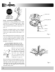
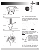
Back o (loosen) the three screws on the electri-
cal housing mounting plate attached to the motor
shaft (see gure 15).
A color coded wire connector (female) is located
inside the electrical switch housing (see gure
14), a male connector extends from the mounting
plate. Align the colors on each connector and
push them together. The connectors are also
notched and will connect only when the colors
are aligned.
Connect the single wire from fan to the single
plug in Switch Housing Unit.
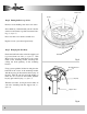
The switch housing has three slotted holes
around the top. Align these holes with the three
screws on the mounting plate. Push the switch
housing up and rotate the the right so the screws
are at the far left of the horizontal slot.
Tighten each screw.
Step 10 Electrical Switch Housing Installation
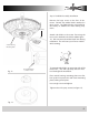
Check all safety pins, set screws and connec-
tions are properly in place and tight.
Check blade clearance and rotation.
Attach the decorative pull chain tassel(s) to the
switch housing.
Step 11 Final Checks
Motor
Housing
Connector
Switch
Housing
Connector
Fig. 14
Switch Housing
Mounting Plate
Molex Plug
(Male and Female)
Switch Housing
Mounting Plate
Screw
Single
Wire
Plugs
Switch
Housing
Screw
Fig. 15