
Owner manual
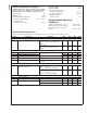
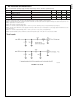
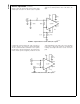
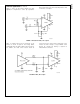
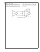

Test Loads (Continued)
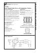
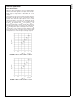
Pin Descriptions
Pin # Name Description
1V
BB
Optional, bias voltage (may be used to bias inputs) - see device operation
section for details. If unused leave as no connect (NC).
2V
IN+
Positive input pin
3V
IN-
Negative input pin
4R
REF
Output driver level control. Connect a resistor to ground to set output voltage
swing.
5V
SS
Negative power supply
6 SDO Serial data true output
7 SDO
Serial data complement output
8V
DD
Positive power supply
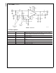
DS101329-3
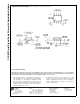
FIGURE 2. Test Circuit
CLC001
www.national.com 4