
Owner manual

Device Operation (Continued)
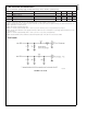
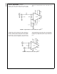
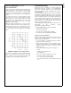
Figure 5
shows the CLC001 with an AC-coupled, single
ended input connection. The 82.5Ω resister in parallel
with 825Ω gives the equivalent termination resistance of
75Ω.R
BB
set at 5kΩ provides 1.25V of DC bias to the
input.
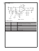
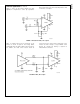
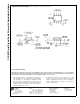
A typical DC-coupled, twisted pair cable connection is
shown in
Figure 6
. The CLC001 is driven differentially.
The line is terminated with a termination resistor equal to
the impedance of the line being driven. The actual resistor
value is media specific, but typically is between 100 and
120Ω depending upon the cable. This resistor should be
located close to the CLC001 inputs pins to minimize the
resulting stub length between the resistor and device
pads.
DS101329-5
FIGURE 5. Single Ended 75Ω Coaxial Cable, AC-coupled
DS101329-6
FIGURE 6. Twisted Pair Cable, DC-coupled
CLC001
www.national.com 6