
Owner manual

Device Operation (Continued)
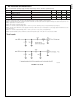
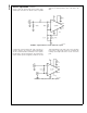
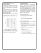
Figure 7
shows an AC-coupled, twisted pair cable
application. It implements a center tap capacitance
termination used in conjunction with two 50Ω resistors to
filter common mode noise. R
BB
set at 5kΩ provides 1.25V
of DC bias to each input.
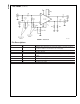
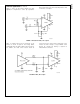
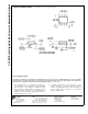
PECL or LVPECL drivers may be interfaced to the
CLC001 as shown in
Figure 8
. The voltage divider
network will reduce the PECL output to the proper levels.
For LVPECL, the 100Ω series resistors should be
removed, since the common mode range inputs of the
CLC001 are wide enough to accept LVPECL levels
directly. No external DC biasing is required for
PECL/LVPECL connections.
DS101329-7
FIGURE 7. Twisted Pair Cable, AC-coupled
DS101329-8
FIGURE 8. PECL, DC-coupled
CLC001
www.national.com7