
Owner manual

Device Operation (Continued)
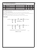
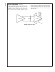
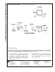
A typical LVDS input connection is shown in
Figure 9
. The
media is driven differentially by an LVDS driver. The line is
terminated with a termination resistor equal to the
impedance of the line being driven. The actual resistor
value is media specific, but typically is between 100 and
120Ω. This resistor should be located close to the
CLC001 inputs pins to minimize the resulting stub length
between the resistor and device pads. The CLC001
supports
±
100mV thresholds across the entire LVDS
common mode range of 0.1V to 2.3V for a 200mV
differential signal.
DS101329-9
FIGURE 9. LVDS, DC-coupled
CLC001
www.national.com 8