
Instruction Manual


DS18S20
10 of 21
every Alarm Search cycle (i.e., Alarm Search command followed by data exchange), the bus master must
return to Step 1 (Initialization) in the transaction sequence. Refer to the OPERATION – ALARM
SIGNALING section for an explanation of alarm flag operation.
DS18S20 FUNCTION COMMANDS
After the bus master has used a ROM command to address the DS18S20 with which it wishes to
communicate, the master can issue one of the DS18S20 function commands. These commands allow the
master to write to and read from the DS18S20’s scratchpad memory, initiate temperature conversions and
determine the power supply mode. The DS18S20 function commands, which are described below, are
summarized in Table 4 and illustrated by the flowchart in Figure 15.
CONVERT T [44h]
This command initiates a single temperature conversion. Following the conversion, the resulting thermal
data is stored in the 2-byte temperature register in the scratchpad memory and the DS18S20 returns to its
low-power idle state. If the device is being used in parasite power mode, within 10 µs (max) after this
command is issued the master must enable a strong pullup on the 1-wire bus for the duration of the
conversion (t
conv
) as described in the POWERING THE DS18S20 section. If the DS18S20 is powered
by an external supply, the master can issue read time slots after the Convert T command and the
DS18S20 will respond by transmitting 0 while the temperature conversion is in progress and 1 when the
conversion is done. In parasite power mode this notification technique cannot be used since the bus is
pulled high by the strong pullup during the conversion.
WRITE SCRATCHPAD [4Eh]
This command allows the master to write 2 bytes of data to the DS18S20’s scratchpad. The first byte is
written into the T
H
register (byte 2 of the scratchpad), and the second byte is written into the T
L
register
(byte 3 of the scratchpad). Data must be transmitted least significant bit first. Both bytes MUST be
written before the master issues a reset, or the data may be corrupted.
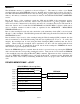
READ SCRATCHPAD [BEh]
This command allows the master to read the contents of the scratchpad. The data transfer starts with the
least significant bit of byte 0 and continues through the scratchpad until the 9
th
byte (byte 8 – CRC) is
read. The master may issue a reset to terminate reading at any time if only part of the scratchpad data is
needed.
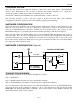
COPY SCRATCHPAD [48h]
This command copies the contents of the scratchpad T
H
and T
L
registers (bytes 2 and 3) to EEPROM. If
the device is being used in parasite power mode, within 10 µs (max) after this command is issued the
master must enable a strong pullup on the 1-wire bus for at least 10 ms as described in the POWERING
THE DS18S20 section.
RECALL E
2
[B8h]
This command recalls the alarm trigger values (T
H
and T
L
) from EEPROM and places the data in bytes 2
and 3, respectively, in the scratchpad memory. The master device can issue read time slots following the
Recall E
2
command and the DS18S20 will indicate the status of the recall by transmitting 0 while the
recall is in progress and 1 when the recall is done. The recall operation happens automatically at power-
up, so valid data is available in the scratchpad as soon as power is applied to the device.
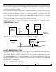
READ POWER SUPPLY [B4h]
The master device issues this command followed by a read time slot to determine if any DS18S20s on the
bus are using parasite power. During the read time slot, parasite powered DS18S20s will pull the bus
low, and externally powered DS18S20s will let the bus remain high. Refer to the POWERING THE
DS18S20 section for usage information for this command.