
Instruction Manual


DS18S20
2 of 21
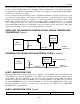
DETAILED PIN DESCRIPTIONS Table 1
8-PIN SOIC* TO-92 SYMBOL DESCRIPTION
5 1 GND
Ground.
4 2 DQ Data Input/Output pin. Open-drain 1-wire interface pin. Also
provides power to the device when used in parasite power mode
(see “Parasite Power” section.)
3 3 V
DD
Optional V
DD
pin. V
DD
must be grounded for operation in
parasite power mode.
*All pins not specified in this table are “No Connect” pins.
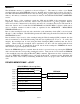
OVERVIEW
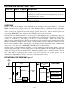
Figure 1 shows a block diagram of the DS18S20, and pin descriptions are given in Table 1. The 64-bit
ROM stores the device’s unique serial code. The scratchpad memory contains the 2-byte temperature
register that stores the digital output from the temperature sensor. In addition, the scratchpad provides
access to the 1-byte upper and lower alarm trigger registers (T
H
and T
L
). The T
H
and T
L
registers are
nonvolatile (EEPROM), so they will retain data when the device is powered down.
The DS18S20 uses Dallas’ exclusive 1-wire bus protocol that implements bus communication using one
control signal. The control line requires a weak pullup resistor since all devices are linked to the bus via a
3-state or open-drain port (the DQ pin in the case of the DS18S20). In this bus system, the
microprocessor (the master device) identifies and addresses devices on the bus using each device’s unique
64-bit code. Because each device has a unique code, the number of devices that can be addressed on one
bus is virtually unlimited. The 1-wire bus protocol, including detailed explanations of the commands and
“time slots,” is covered in the 1-WIRE BUS SYSTEM section of this datasheet.
Another feature of the DS18S20 is the ability to operate without an external power supply. Power is
instead supplied through the 1-wire pullup resistor via the DQ pin when the bus is high. The high bus
signal also charges an internal capacitor (C
PP
), which then supplies power to the device when the bus is
low. This method of deriving power from the 1-wire bus is referred to as “parasite power.” As an
alternative, the DS18S20 may also be powered by an external supply on V
DD
.
DS18S20 BLOCK DIAGRAM Figure 1
V
PU
4.7K
POWER
SUPPLY
SENSE
64-BIT ROM
AND
1-wire PORT
D
Q
V
DD
INTERNAL V
DD
C
PP
PARASITE POWER
CIRCUIT
MEMORY CONTROL
LOGIC
SCRATCHPAD
8-BIT CRC GENERATOR
TEMPERATURE SENSOR
ALARM HIGH TRIGGER (T
H
)
REGISTER (EEPROM)
ALARM LOW TRIGGER (T
L
)
REGISTER (EEPROM)
GND
DS18S20