
Instruction Manual


DS18S20
4 of 21
OPERATION – ALARM SIGNALING
After the DS18S20 performs a temperature conversion, the temperature value is compared to the user-
defined two’s complement alarm trigger values stored in the 1-byte T
H
and T
L
registers (see Figure 3).
The sign bit (S)
indicates if the value is positive or negative: for positive numbers S = 0 and for negative
numbers S = 1. The T
H
and T
L
registers are nonvolatile (EEPROM) so they will retain data when the
device is powered down. T
H
and T
L
can be accessed through bytes 2 and 3 of the scratchpad as explained
in the MEMORY section of this datasheet.
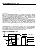
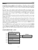
T
H
AND T
L
REGISTER FORMAT Figure 3
bit 7 bit 6 bit 5 bit 4 bit 3 bit 2 bit 1 bit 0
S 2
6
2
5
2
5
2
5
2
2
2
1
2
0
Only bits 8 through 1 of the temperature register are used in the T
H
and T
L
comparison since T
H
and T
L
are 8-bit registers. If the result of a temperature measurement is higher than T
H
or lower than T
L
, an
alarm condition exists and an alarm flag is set inside the DS18S20. This flag is updated after every
temperature measurement; therefore, if the alarm condition goes away, the flag will be turned off after the
next temperature conversion.
The master device can check the alarm flag status of all DS18S20s on the bus by issuing an Alarm Search
[ECh] command. Any DS18S20s with a set alarm flag will respond to the command, so the master can
determine exactly which DS18S20s have experienced an alarm condition. If an alarm condition exists
and the T
H
or T
L
settings have changed, another temperature conversion should be done to validate the
alarm condition.
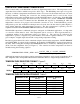
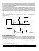
POWERING THE DS18S20
The DS18S20 can be powered by an external supply on the V
DD
pin, or it can operate in “parasite power”
mode, which allows the DS18S20 to function without a local external supply. Parasite power is very
useful for applications that require remote temperature sensing or that are very space constrained. Figure
1 shows the DS18S20’s parasite-power control circuitry, which “steals” power from the 1-wire bus via
the DQ pin when the bus is high. The stolen charge powers the DS18S20 while the bus is high, and some
of the charge is stored on the parasite power capacitor (C
PP
) to provide power when the bus is low.
When the DS18S20 is used in parasite power mode, the V
DD
pin must be connected to ground.
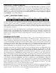
In parasite power mode, the 1-wire bus and C
PP
can provide sufficient current to the DS18S20 for most
operations as long as the specified timing and voltage requirements are met (refer to the DC
ELECTRICAL CHARACTERISTICS and the AC ELECTRICAL CHARACTERISTICS sections of this
data sheet). However, when the DS18S20 is performing temperature conversions or copying data from
the scratchpad memory to EEPROM, the operating current can be as high as 1.5 mA. This current can
cause an unacceptable voltage drop across the weak 1-wire pullup resistor and is more current than can be
supplied by C
PP
. To assure that the DS18S20 has sufficient supply current, it is necessary to provide a
strong pullup on the 1-wire bus whenever temperature conversions are taking place or data is being
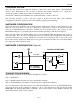
copied from the scratchpad to EEPROM. This can be accomplished by using a MOSFET to pull the bus
directly to the rail as shown in Figure 4. The 1-wire bus must be switched to the strong pullup within 10
µs (max) after a Convert T [44h] or Copy Scratchpad [48h] command is issued, and the bus must be held
high by the pullup for the duration of the conversion (t
conv
) or data transfer (t
wr
= 10 ms). No other
activity can take place on the 1-wire bus while the pullup is enabled.
The DS18S20 can also be powered by the conventional method of connecting an external power supply to
the V
DD
pin, as shown in Figure 5. The advantage of this method is that the MOSFET pullup is not
required, and the 1–wire bus is free to carry other traffic during the temperature conversion time.