
Instruction Manual


DS18S20
6 of 21
MEMORY
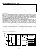
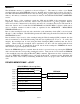
The DS18S20’s memory is organized as shown in Figure 7. The memory consists of an SRAM
scratchpad with nonvolatile EEPROM storage for the high and low alarm trigger registers (T
H
and T
L
).
Note that if the DS18S20 alarm function is not used, the T
H
and T
L
registers can serve as general-purpose
memory. All memory commands are described in detail in the DS18S20 FUNCTION COMMANDS
section.
Byte 0 and byte 1 of the scratchpad contain the LSB and the MSB of the temperature register,
respectively. These bytes are read-only. Bytes 2 and 3 provide access to T
H
and T
L
registers. Bytes 4
and 5 are reserved for internal use by the device and cannot be overwritten; these bytes will return all 1s
when read. Bytes 6 and 7 contain the COUNT REMAIN and COUNT PER ºC registers, which can be
used to calculate extended resolution results as explained in the OPERATION – MEASURING
TEMPERATURE section.
Byte 8 of the scratchpad is read-only and contains the cyclic redundancy check (CRC) code for bytes 0
through 7 of the scratchpad. The DS18S20 generates this CRC using the method described in the CRC
GENERATION section.
Data is written to bytes 2 and 3 of the scratchpad using the Write Scratchpad [4Eh] command; the data
must be transmitted to the DS18S20 starting with the least significant bit of byte 2. To verify data
integrity, the scratchpad can be read (using the Read Scratchpad [BEh] command) after the data is
written. When reading the scratchpad, data is transferred over the 1-wire bus starting with the least
significant bit of byte 0. To transfer the T
H
and T
L
data from the scratchpad to EEPROM, the master
must issue the Copy Scratchpad [48h] command.
Data in the EEPROM registers is retained when the device is powered down; at power-up the EEPROM
data is reloaded into the corresponding scratchpad locations. Data can also be reloaded from EEPROM
to the scratchpad at any time using the Recall E
2
[B8h] command. The master can issue “read time slots”
(see the 1-WIRE BUS SYSTEM section) following the Recall E
2
command and the DS18S20 will
indicate the status of the recall by transmitting 0 while the recall is in progress and 1 when the recall is
done.
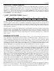
DS18S20 MEMORY MAP cáÖìêÉ=T
SCRATCHPAD (Power-up State)
byte 0 Temperature LSB (AAh)
byte 1 Temperature MSB (00h)
EEPROM
byte 2 T
H
Register or User Byte 1* T
H
Register or User Byte 1
byte 3 T
L
Register or User Byte 2* T
L
Register or User Byte 2
byte 4 Reserved (FFh)
byte 5 Reserved (FFh)
byte 6 COUNT REMAIN (0Ch)
byte 7 COUNT PER °C (10h)
byte 8 CRC*
*Power-up state depends on value(s) stored
in EEPROM
(85°C)