
Instruction Manual


DS18S20
8 of 21
1-WIRE BUS SYSTEM
The 1-wire bus system uses a single bus master to control one or more slave devices. The DS18S20 is
always a slave. When there is only one slave on the bus, the system is referred to as a “single-drop”
system; the system is “multi-drop” if there are multiple slaves on the bus.
All data and commands are transmitted least significant bit first over the 1-wire bus.
The following discussion of the 1-wire bus system is broken down into three topics: hardware
configuration, transaction sequence, and 1-wire signaling (signal types and timing).
HARDWARE CONFIGURATION
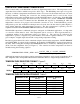
The 1-wire bus has by definition only a single data line. Each device (master or slave) interfaces to the
data line via an open drain or 3–state port. This allows each device to “release” the data line when the
device is not transmitting data so the bus is available for use by another device. The 1-wire port of the
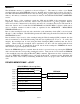
DS18S20 (the DQ pin) is open drain with an internal circuit equivalent to that shown in Figure 9.
The 1-wire bus requires an external pullup resistor of approximately 5 kΩ; thus, the idle state for the 1-
wire bus is high. If for any reason a transaction needs to be suspended, the bus MUST be left in the idle
state if the transaction is to resume. Infinite recovery time can occur between bits so long as the 1-wire
bus is in the inactive (high) state during the recovery period. If the bus is held low for more than 480 µs,
all components on the bus will be reset.
HARDWARE CONFIGURATION Figure=V=
TRANSACTION SEQUENCE
The transaction sequence for accessing the DS18S20 is as follows:
Step 1. Initialization
Step 2. ROM Command (followed by any required data exchange)
Step 3. DS18S20 Function Command (followed by any required data exchange)
It is very important to follow this sequence every time the DS18S20 is accessed, as the DS18S20 will not
respond if any steps in the sequence are missing or out of order. Exceptions to this rule are the Search
ROM [F0h] and Alarm Search [ECh] commands. After issuing either of these ROM commands, the
master must return to Step 1 in the sequence.
V
PU
4.7K
5 µA
Typ.
R
X
T
X
DS18S20 1-WIRE PORT
100 Ω
ΩΩ
Ω
M
OS
FET
T
X
R
X
R
X
= RECEIVE
T
X
= TRANSMIT
1-wire Bus
DQ
Pin