
User Manual


DS2401
2 of 10
DESCRIPTION
The DS2401 enhanced Silicon Serial Number is a low-cost, electronic registration number that provides
an absolutely unique identity which can be determined with a minimal electronic interface (typically, a
single port pin of a microcontroller). The DS2401 consists of a factory-lasered, 64-bit ROM that includes
a unique 48-bit serial number, an 8-bit CRC, and an 8-bit Family Code (01h). Data is transferred serially
via the 1-Wire protocol that requires only a single data lead and a ground return. Power for reading and
writing the device is derived from the data line itself with no need for an external power source. The
DS2401 is an upgrade to the DS2400. The DS2401 is fully reverse-compatible with the DS2400 but
provides the additional multi-rop capability that enables many devices to reside on a single data line. The
familiar TO-92, SOT-223 or TSOC package provides a compact enclosure that allows standard assembly
equipment to handle the device easily.
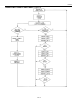
OPERATION
The DS2401’s internal ROM is accessed via a single data line. The 48-bit serial number, 8-bit family
code and 8-bit CRC are retrieved using the Dallas 1-Wire protocol. This protocol defines bus transactions
in terms of the bus state during specified time slots that are initiated on the falling edge of sync pulses
from the bus master. All data is read and written least significant bit first.
1-WIRE BUS SYSTEM
The 1-Wire bus is a system which has a single bus master system and one or more slaves. In all instances,
the DS2401 is a slave device. The bus master is typically a microcontroller. The discussion of this bus
system is broken down into three topics: hardware configuration, transaction sequence, and 1-Wire
signaling (signal type and timing). For a more detailed protocol description, refer to Chapter 4 of the
Book of DS19xx iButton
®
Standards.
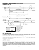
Hardware Configuration
The 1-Wire bus has only a single line by definition; it is important that each device on the bus be able to
drive it at the appropriate time. To facilitate this, each device attached to the 1-Wire bus must have an
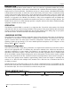
open-drain connection or 3-state outputs. The DS2401 is an open-drain part with an internal circuit
equivalent to that shown in Figure 2. The bus master can be the same equivalent circuit. If a bidirectional
pin is not available, separate output and input pins can be tied together. The bus master requires a pullup
resistor at the master end of the bus, with the bus master circuit equivalent to the one shown in Figure 3.
The value of the pullup resistor should be approximately 5kW for short line lengths. A multidrop bus
consists of a 1-Wire bus with multiple slaves attached. The 1-Wire bus has a maximum data rate of
16.3kbits per second.
The idle state for the 1-Wire bus is high. If, for any reason, a transaction needs to be suspended, the bus
MUST be left in the idle state if the transaction is to resume. If this does not occur and the bus is left low
for more than 120ms, one or more of the devices on the bus may be reset.
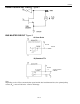
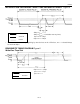
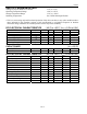
DS2401 MEMORY MAP Figure 1
8-Bit CRC Code 48-Bit Serial Number 8-Bit Family Code (01h)
MSB LSB MSB LSB MSB LSB
iButton is a registered trademark of Dallas Semiconductor.