
User Manual


DS2401
5 of 10
1-WIRE SIGNALING
The DS2401 requires a strict protocol to ensure data integrity. The protocol consists of four types of
signaling on one line: reset sequence with Reset Pulse and Presence Pulse, write 0, write 1, and read data.
All these signals except Presence Pulse are initiated by the bus master.
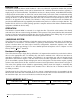
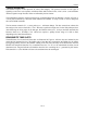
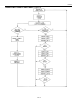
The initialization sequence required to begin any communication with the DS2401 is shown in Figure 5.
A reset pulse followed by a Presence Pulse indicates the DS2401 is ready to send or receive data given
the correct ROM command.
The bus master transmits (T
X
) a reset pulse (t
RSTL
, minimum 480ms). The bus master then releases the
line and goes into receive mode (R
X
). The 1-Wire bus is pulled to a high state via the 5kW pullup resistor.
After detecting the rising edge on the data pin, the DS2401 waits (t
PDH
, 15-60ms) and then transmits the
Presence Pulse (t
PDL
, 60-240ms). The 1-Wire bus requires a pullup resistor range of 1.5kW to 5kW,
depending on bus load characteristics.
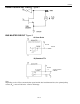
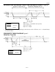
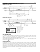
READ/WRITE TIME SLOTS
The definitions of write and read time slots are illustrated in Figure 6. All time slots are initiated by the
master driving the data line low. The falling edge of the data line synchronizes the DS2401 to the master
by triggering a delay circuit in the DS2401. During write time slots, the delay circuit determines when the
DS2401 will sample the data line. For a read data time slot, if a “0” is to be transmitted, the delay circuit
determines how long the DS2401 will hold the data line low overriding the “1” generated by the master.
If the data bit is a 1, the DS2401 will leave the read data time slot unchanged.