
User Manual


DS2401
8 of 10
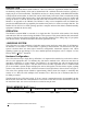
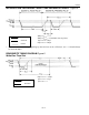
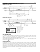
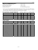
READ/WRITE TIMING DIAGRAM (cont’d) Figure 6
Write-zero Time Slot
60ms £ t
LOW0
< t
SLOT
< 120ms
1ms £ t
REC
< ¥
Read-data Time Slot
60ms £ t
SLOT
< 120ms
1ms £ t
LOWR
< 15ms
0 £ t
RELEASE
< 45ms
1ms £ t
REC
< ¥
t
RDV
= 15ms
t
SU
< 1ms
CRC GENERATION
To validate the data transmitted from the DS2401, the bus master may generate a CRC value from the
data as it is received. This generated value is compared to the value stored in the last 8 bits of the
DS2401. If the two CRC values match, the transmission is error-free.
The equivalent polynomial function of this CRC is: CRC = x
8
+ x
5
+ x
4
+ 1. For more details, see the
Book of DS19xx iButton Standards.
CUSTOM DS2401
Customization of a portion of the unique 48-bit serial number by the customer is available. Dallas
Semiconductor will register and assign a specific customer ID in the 12 most significant bits of the 48-bit
field. The next most significant bits are selectable by the customer as a starting value, and the least
significant bits are non-selectable and will be automatically incremented by one. Certain quantities and
conditions apply for these custom parts. Contact your Dallas Semiconductor sales representative for more
information.
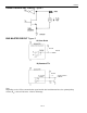
RESISTOR
MASTER
DS2401