
Manual


DS2740
12 of 15
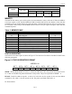
Table 4. FUNCTION COMMANDS
COMMAND DESCRIPTION
COMMAND
PROTOCOL
BUS STATE
AFTER COMMAND
PROTOCOL
BUS DATA
Read Data
Reads data from
memory starting at
address XX
69h, XX Master Rx
Up to 256 bytes
of data
Write Data
Writes data to memory
starting at address XX
6Ch, XX Master Tx
Up to 256 bytes
of data
1-WIRE SIGNALING
The 1-Wire bus requires strict signaling protocols to ensure data integrity. The four protocols used by the
DS2740 are as follows: the initialization sequence (reset pulse followed by presence pulse), write 0, write
1, and read data. All of these types of signaling except the presence pulse are initiated by the bus master.
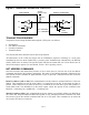
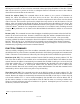
The initialization sequence required to begin any communication with the DS2740 is shown in Figure 11.
A presence pulse following a reset pulse indicates that the DS2740 is ready to accept a net address
command. The bus master transmits (Tx) a reset pulse for t
RSTL
. The bus master then releases the line and
goes into receive mode (Rx). The 1-Wire bus line is then pulled high by the pullup resistor. After
detecting the rising edge on the DQ pin, the DS2740 waits for t
PDH
and then transmits the presence pulse
for t
PDL
.
Figure 11. 1-WIRE INITIALIZATION SEQUENCE
WRITE-TIME SLOTS
A write-time slot is initiated when the bus master pulls the 1-Wire bus from a logic-high (inactive) level
to a logic-low level. There are two types of write-time slots: write 1 and write 0. All write-time slots must
be t
SLOT
in duration with a 1ms minimum recovery time, t
REC
, between cycles. The DS2740 samples the
1-Wire bus line between 15
ms and 60ms (between 2ms and 6ms for overdrive speed) after the line falls. If
the line is high when sampled, a write 1 occurs. If the line is low when sampled, a write 0 occurs (see
Figure 12). For the bus master to generate a write 1 time slot, the bus line must be pulled low and then
released, allowing the line to be pulled high within 15
ms (2ms for overdrive speed) after the start of the
write-time slot. For the host to generate a write 0 time slot, the bus line must be pulled low and held low
for the duration of the write-time slot.
t
R
S
TL
t
PDL
t
R
S
TH
t
PDH
PACK+
PACK-
LINE TYPE LEGEND:
BUS MASTER ACTIVE LOW
DS2740 ACTIVE LOW
RESISTOR PULLUP
BOTH BUS MASTER AND
DS2740 ACTIVE LOW
DQ