
Manual


DS2740
13 of 15
READ-TIME SLOTS
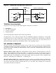
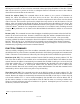
A read-time slot is initiated when the bus master pulls the 1-Wire bus line from a logic-high level to a
logic-low level. The bus master must keep the bus line low for at least 1ms and then release it to allow the
DS2740 to present valid data. The bus master can then sample the data t
RDV
from the start of the read-
time slot. By the end of the read-time slot, the DS2740 releases the bus line and allows it to be pulled
high by the external pullup resistor. All read-time slots must be t
SLOT
in duration with a 1ms minimum
recovery time, t
REC
, between cycles. See Figure 12 for more information.
Figure 12. 1-WIRE WRITE- AND READ-TIME SLOTS
LINE TYPE LEGEND:
Bus master active low
DS2740 active low
Resistor pullup
Both bus master and
DS2740 active low
t
SLOT
V
PULLUP
GND
READ 0 SLOT
READ 1 SLOT
t
SLOT
t
REC
>1
m
s
t
RDV
Master Sample Window
Master Sample Window
t
RDV
V
PULLUP
GND
t
SLOT
Standard
t
LOW1
t
SLOT
WRITE 0 SLOT WRITE 1 SLOT
t
LOW0
t
REC
>1
m
s
DS2740 Sample Window
MIN TYP MA
X
15
m
s15
m
s 30
m
s
DS2740 Sample Window
MIN TYP MA
X
15
m
s15
m
s 30
m
s
2
m
s
Overdrive
Mode
1
m
s 3
m
s 1
m
s2
m
s 3
m
s