
Manual


DS2740
14 of 15
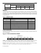
ABSOLUTE MAXIMUM RATINGS*
Voltage on V
DD
, DQ, IS1, IS2, PIO, Relative to V
SS
-0.3V to +6V
Voltage on SNS, Relative to V
SS
-0.3V to +6V
Operating Temperature Range -40°C to +85°C
Storage Temperature Range -55°C to +125°C
Soldering Temperature See IPC/JEDECJ-STD-020A
* This is a stress rating only and functional operation of the device at these or any other conditions above
those indicated in the operation sections of this specification is not implied. Exposure to absolute
maximum rating conditions for extended periods of time may affect reliability.
RECOMMENDED DC OPERATING CONDITIONS
(2.7V £ V
DD
£ 5.5V; T
A
= 0°C to +70°C.)
PARAMETER SYMBOL CONDITIONS MIN TYP MAX UNITS
Supply Voltage V
DD
(Note 1) 2.7 5.5 V
Data Pin DQ (Note 1) -0.3 +5.5 V
DC ELECTRICAL CHARACTERISTICS
(2.7V £ V
DD
£ 4.2V; T
A
= 0°C to +70°C.)
PARAMETER SYMBOL CONDITIONS MIN TYP MAX UNITS
50 65
Active Current I
ACTIVE
V
DD
= 5.5V 85
mA
V
DD
= 2.0V,
DQ = PIO = V
SS
0.6 1.0
Sleep-Mode Current I
SLEEP
V
DD
= 4.2V,
DQ = PIO = V
SS
0.9 1.25
mA
Undervoltage Sleep
Threshold
V
UV
2.3 2.5 2.7 V
DS2740 1.56
Current Resolution I
LSB
DS27640B 6.25
mV
Current Full-Scale
Magnitude
I
FS
51.2
mV
DS2740 (Note 2) -3 +1 +5Current Measurement
Offset (Auto
Calibrated)
I
OERR
DS2740B (Note 2) -2 0 +2
LSb
Current Gain Error I
GERR
-1 +1
% of
reading
Accumulated Current
Resolution
q
CA
6.25
mVh
Current Sample Clock
Frequency
f
SAMP
18.6 kHz
V
DD
= 3.5V at +25°C -1 +1
Timebase Accuracy t
ERR
-4 +4
%
Input Logic High:
OVD
V
IH
(Note 1)
V
DD
-
0.2V
V
Input Logic High: DQ,
PIO
V
IH
(Note 1) 1.5 V
Input Logic Low:
OVD
V
IL
(Note 1)
V
SS
+ 0.2
V