
Manual


DS2740
7 of 15
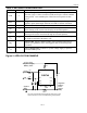
SPECIAL FEATURE REGISTER
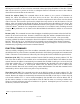
The format of the special feature register is shown in Figure 6. The function of each bit is described in
detail in the following paragraphs.
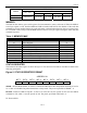
Figure 6. SPECIAL FEATURE REGISTER FORMAT
ADDRESS 08
BIT 7 BIT 6 BIT 5 BIT 4 BIT 3 BIT 2 BIT 1 BIT 0
X
PIO X X X X X X
PIO—PIO Pin Sense and Control. This bit is read and write enabled. Writing a 0 to the PIO bit enables
the PIO open-drain output driver, forcing the PIO pin low. Writing a 1 to the PIO bit disables the output
driver, allowing the PIO pin to be pulled high or used as an input. Reading the PIO bit returns the logic
level forced on the PIO pin. Note that if PIO is left floating, the weak pulldown brings the pin low.
X—Reserved Bits.
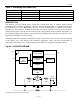
1-WIRE BUS SYSTEM
The 1-Wire bus is a system that has a single bus master and one or more slaves. A multidrop bus is a
1-Wire bus with multiple slaves. A single-drop bus has only one slave device. In all instances, the
DS2740 is a slave device. The bus master is typically a microprocessor in the host system. The discussion
of this bus system consists of four topics: 64-bit net address, hardware configuration, transaction
sequence, and 1-Wire signaling.
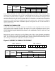
64-BIT NET ADDRESS
Each DS2740 has a unique, factory-programmed 1-Wire net address that is 64 bits in length. The first
eight bits are the 1-Wire family code (36h for DS2740). The next 48 bits are a unique serial number. The
last eight bits are a cyclic redundancy check (CRC) of the first 56 bits (see Figure 7). The 64-bit net
address and the 1-Wire I/O circuitry built into the device enable the DS2740 to communicate through the
1-Wire protocol detailed in the 1-Wire Bus System section of this data sheet.
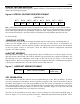
Figure 7. 1-WIRE NET ADDRESS FORMAT
8-BIT CRC 48-BIT SERIAL NUMBER
8-BIT FAMILY
CODE (36h)
MSb LSb
CRC GENERATION
The DS2740 has an 8-bit CRC stored in the most significant byte of its 1-Wire net address. To ensure
error-free transmission of the address, the host system can compute a CRC value from the first 56 bits of
the address and compare it to the CRC from the DS2740. The host system is responsible for verifying the
CRC value and taking action as a result. The DS2740 does not compare CRC values and does not prevent
a command sequence from proceeding as a result of a CRC mismatch. Proper use of the CRC can result
in a communication channel with a very high level of integrity.
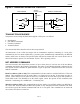
The CRC can be generated by the host using a circuit consisting of a shift register and XOR gates as
shown in Figure 8, or it can be generated in software. Additional information about the Dallas 1-Wire