
Manual


DS2740
9 of 15
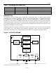
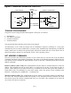
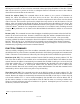
Figure 9. 1-WIRE BUS INTERFACE CIRCUITRY
TRANSACTION SEQUENCE
The protocol for accessing the DS2740 through the 1-Wire port is as follows:
§ Initialization
§ Net Address Command
§ Function Command
§ Transaction/Data
The sections that follow describe each of these steps in detail.
All transactions of the 1-Wire bus begin with an initialization sequence consisting of a reset pulse
transmitted by the bus master followed by a presence pulse simultaneously transmitted by the DS2740
and any other slaves on the bus. The presence pulse tells the bus master that one or more devices are on
the bus and ready to operate. For more details, see the 1-Wire Signaling section.
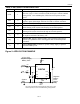
NET ADDRESS COMMANDS
Once the bus master has detected the presence of one or more slaves, it can issue one of the net address
commands described in the following paragraphs. The name of each ROM command is followed by the
8-bit opcode for that command in square brackets. Figure 10 presents a transaction flowchart of the net
address commands.
Read Net Address [33h or 39h]. This command allows the bus master to read the DS2740’s 1-Wire net
address. This command can only be used if there is a single slave on the bus. If more than one slave is
present, a data collision occurs when all slaves try to transmit at the same time (open drain produces a
wired-AND result). The RNAOP bit in the status register selects the opcode for this command, with
RNAOP = 0 indicating 33h, and RNAOP = 1 indicating 39h.
Match Net Address [55h]. This command allows the bus master to specifically address one DS2740 on
the 1-Wire bus. Only the addressed DS2740 responds to any subsequent function command. All other
slave devices ignore the function command and wait for a reset pulse. This command can be used with
one or more slave devices on the bus.
1mA
(typ)
100W
MOSFET
Tx
RxRx
Tx
Rx = RECEIVE
Tx = TRANSMIT
Vpullup
(2.0V to 5.5V)
4.7kW
BUS MASTER DS2740 1-WIRE PORT