
Owner's manual


MAX4162/MAX4163/MAX4164
UCSP, Micropower, Single-Supply, 10V,
Rail-to-Rail I/O Op Amps
______________________________________________________________________________________ 11
1) The on-board charge pumps generate a small
amount of 700kHz switching noise at the op amp’s
output. The amplitude of this noise is typically
100µV
P-P
. The noise is not referred to the input, and
is independent of amplifier gain. The charge-pump
switching frequency is well beyond the amplifier’s
200kHz bandwidth, and is therefore unnoticeable in
most applications.
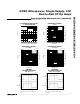
2) The charge pumps typically require up to 20µs on
power-up to fully energize the internal supply rails
(Figure 3).
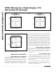
Power Supplies and Layout
The MAX4162/MAX4163/MAX4164 are guaranteed to
operate from a single 2.7V to 10.0V power supply, but
full rail-to-rail operation typically extends below 2V. For
single-supply operation, bypass the power supply with a
1µF capacitor in parallel with a 0.1µF ceramic capacitor.
If operating from dual supplies, bypass each supply to
ground.
Good layout improves performance by decreasing the
amount of stray capacitance at the op amp’s inputs and
output. To decrease stray capacitance, minimize both
trace and external component lead lengths, and place
external components close to the op amp’s pins.
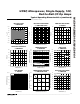
UCSP Package Consideration
For general UCSP package information and PC layout
considerations, please refer to the Maxim Application
Note (Wafer-Level Ultra-Chip-Board-Scale-Package).
UCSP Reliability
The UCSP represents a unique packaging form factor
that may not perform equally to a packaged product
through traditional mechanical reliability tests. UCSP
reliability is integrally linked to the user’s assembly
methods, circuit board material, and usage environ-
ment. The user should closely review these areas when
considering use of a UCSP. Performance through oper-
ating life test and moisture resistance remains uncom-
promised as it is primarily determined by the
wafer-fabrication process. Mechanical stress perfor-
mance is a greater consideration for a UCSP package.
UCSPs are attached through direct solder contact to
the user’s PC board, foregoing the inherent stress relief
of a packaged product lead frame. Solder joint contact
integrity must be considered.
Table 1 shows the testing done to characterize the
UCSP reliability performance. In conclusion, the UCSP
is capable of performing reliably through environmental
stresses as indicated by the results in the table.
Additional usage data and recommendations are
detailed in the UCSP application note, which can be
found on Maxim’s website at www.maxim-ic.com.
TEST CONDITIONS DURATION
NO. OF FAILURES PER
SAMPLE SIZE
Temperature Cycle -35°C to +85°C, -40°C to +100°C 150 cycles, 900 cycles 0/10, 0/200
Operating Life
T
A
= +70°C
240h 0/10
Moisture Resistance -20°C to +60°C, 90% RH 240h 0/10
Low-Temperature Storage -20°C 240h 0/10
Low-Temperature Operational -10°C 24h 0/10
Solderability 8h steam age — 0/15
ESD ±2000V, Human Body Model — 0/5
High-Temperature Operating
Life
T
J
= +150°C
168h 0/45
Table 1. Reliability Test Data