
User Manual


MAX4165–MAX4169
High-Output-Drive, Precision, Low-Power, Single-
Supply, Rail-to-Rail I/O Op Amps with Shutdown
12 ______________________________________________________________________________________
Power-Up and Shutdown Modes
The MAX4166/MAX4168 have a shutdown option.
When the shutdown pin (SHDN) is pulled low, supply
current drops to 58µA per amplifier (V
CC
= +5V), the
amplifiers are disabled, and their outputs are placed in
a high-impedance state. Pulling SHDN high or leaving it
floating enables the amplifier. In the dual MAX4168, the
two amplifiers shut down independently. Figures 12
and 13 show the MAX4166’s output voltage and sup-
ply-current responses to a shutdown pulse. The
MAX4166–MAX4169 typically settle within 5µs after
power-up (Figure 14).
Power Supplies and Layout
The MAX4165–MAX4169 can operate from a single
+2.7V to +6.5V supply, or from dual ±1.35V to
±3.25V supplies. For single-supply operation, bypass
the power supply with a 0.1µF ceramic capacitor in
parallel with at least 1µF. For dual-supply operation,
bypass each supply to ground. Good layout improves
performance by decreasing the amount of stray capac-
itance at the op amps’ inputs and outputs. Decrease
stray capacitance by placing external components
close to the op amps’ pins, minimizing trace and lead
lengths.
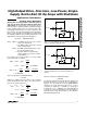
1300
0
10 100k
100
200
300
400
1100
1200
MAX4165-fig08
RESISTIVE LOAD (kΩ)
CAPACITIVE LOAD (pF)
100 1k 10k
1000
900
800
700
600
500
STABLE REGION
V
CC
= +5.0V
R
L
to V
CC
/ 2
UNSTABLE REGION
Figure 8. Capacitive Load Stability
IN
(20mV/div)
OUT
(20mV/div)
MAX4165-fig09
TIME (1µs/div)
V
CC
= +3.0V, C
L
= 1500pF
R
L
= 100kΩ, R
ISO
= 0Ω
Figure 9. Small-Signal Transient Response with Excessive
Capacitive Load
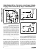
IN
(20mV/div)
OUT
(20mV/div)
MAX4165-fig10
TIME (1µs/div)
V
CC
= +3.0V, C
L
= 1500pF
R
L
= 100kΩ, R
ISO
= 39Ω
Figure 10. Small-Signal Transient Response with Excessive
Capacitive Load with Isolation Resistor
R
ISO
C
L
Figure 11. Capacitive-Load-Driving Circuit