
Owner manual

Manual-3
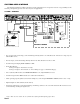
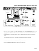
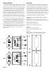
CP 64 REAR PANEL
햲 CHASSIS GROUND SCREW provides a convenient earth (technical) ground connection point. The CP 64 does not
ground the chassis through the power cord. It is important that the unit be grounded.
햳 POWER jack accepts the cable from a Rane RS 1 remote power supply (included) or an available Rane RAP 10 power
supply. This is not a telephone jack. Use of a supply not approved by Rane may damage your unit and void the warranty.
햴 REMOTES port provides the wiring interface for two optional ZR 1 wired remotes. Each ZR 1 remote provides remote
control of Zone Level and Zone Program Select functions. Refer to page Manual-9 for details.
햵 ZONE OUTPUT ports feature balanced, cross-coupled line drivers with Euroblock connectors. These Outputs may be
operated balanced or unbalanced. Zone 1 is stereo. Zone 2 is mono.
햶 ZONE LIMIT threshold controls set the maximum output level for a Zone. These Limiter circuits are true voltage limiters
with a ratio of 15:1. The threshold range is −20 dBu to +20 dBu
햷 ZONE EXPAND OUTPUT ports feature balanced, cross-coupled line drivers with Euroblock connectors. These outputs
may be operated balanced or unbalanced. Zone Expand Outputs are mono.
햸 ZONE EXPAND switches assign Page-only, Program-only or full Zone as the source for each Zone’s Expand Output.
햹 PROGRAM PRIORITY ASSIGN switch determines in which Zone(s) the automatic priority override is enabled. Off
(none), Zone 1, Zone 2 or Both are the possible settings. If you do not intend to use the Priority (“P”) Input as an automatic
override Input, do not assign it with this switch. Use the Zone PROGRAM SELECT switch on the front panel.
햺 Four PROGRAM INPUTS are provided. Three are non-priority Inputs. The fourth is a Program Priority Input. When
signal is present at the Program Priority Input, it is automatically selected as the Input source in the Zone(s) it is assigned
with the Program PRIORITY ASSIGN switch.
햻 RMT ZONE ASSIGN port provides the interface for the PR 2 wired remote. The PR 2 remote is used for Zone assignment
of Page Inputs. Refer to page Manual-9 for details.
햽 PAGING DETECT THRESHOLD sets the Page signal level required to gate a Page on and light the ACTIVE indicator.
The range is −∞ (on) to +4 dBu.
햾 The PAGING OVERLOAD indicator lights when either of the Page Input preamplifiers comes within 3 dB of clipping.
햿 PAGING INPUT TRIM controls adjust Page Input preamplifier gain to match the microphone/source in use, not to set the
page level in the Zones. The range is 30 dB to 60 dB.
헀 PAGING INPUT Euroblock connector provides access to the two balanced instrumentation Paging amplifiers. These
Inputs may be operated balanced or unbalanced.
헁 PAGING INPUT MIC/LINE switches select 30 dB Input Pads when set to LINE. Phantom Power is disabled when LINE
is selected.