SERVICE INSTRUCTION LN-9230-00.1 AEROBELLTM COPESTM** MODEL: 75850 IMPORTANT: Before using this equipment, carefully read SAFETY PRECAUTIONS, starting on page 1, and all instructions in this manual. Keep this Service Bulletin for future reference.
Aerobell Copes - Contents CONTENTS SAFETY: PAGE 1-5 SAFETY PRECAUTIONS............................................................................................................ HAZARDS / SAFEGUARDS........................................................................................................ 1 2 INTRODUCTION: 6-9 GENERAL DESCRIPTION.......................................................................................................... FEATURES.............................................
Aerobell Copes - Contents CONTENTS (Cont.) MAINTENANCE: PAGE 18-23 CLEANING PROCEDURES...................................................................................................... VIBRATION NOISE.................................................................................................................... PREVENTIVE MAINTENANCE................................................................................................. MEAN TIME BETWEEN FAILURE...........................................
Aerobell Copes - Safety SAFETY SAFETY PRECAUTIONS Before operating, maintaining or servicing any Ransburg electrostatic coating system, read and understand all of the technical and safety literature for your Ransburg products. This manual contains information that is important for you to know and understand. This information relates to USER SAFETY and PREVENTING EQUIPMENT PROBLEMS. To help you recognize this information, we use the following symbols. Please pay particular attention to these sections.
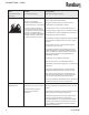
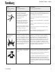
Aerobell Copes - Safety AREA HAZARD SAFEGUARDS Tells where hazards Tells what the hazard is. Tells how to avoid the hazard. Fire Hazard Fire extinguishing equipment must be present in the spray area and tested periodically. may occur. Spray Area Improper or inadequate operationing and maintenance Spray areas must be kept clean to prevent the procedures will cause a fire hazard. accumulation of combustible residues.
Aerobell Copes - Safety AREA HAZARD SAFEGUARDS Tells where hazards Tells what the hazard is. Tells how to avoid the hazard. High voltage equipment is utilized. Arcing in areas of flammable or combustible materials may occur. Personnel are exposed to high voltage during operation and maintenance. The power supply, optional remote control cabinet, and all other electrical equipment must be located outside Class I or II, Division 1 and 2 hazardous areas. Refer to NFPA No. 33, 1995 Edition.
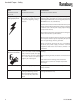
Aerobell Copes - Safety AREA HAZARD SAFEGUARDS Tells where hazards Tells what the hazard is. Tells how to avoid the hazard. This is a high voltage ungrounded device that can produce electrical arcs capable of igniting coating materials. Parts being sprayed must be supported on conveyors or hangers and be grounded. The resistance between the part and ground must not exceed 1 megohm. (Reference NFPA Bulletin No. 33, 1995 Edition.) may occur.
Aerobell Copes - Safety NOTES: LN-9230-00.
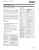
Aerobell Copes - Introduction INTRODUCTION GENERAL DESCRIPTION Turbine Speed: 10,000-50,000 rpm 60,000 rpm max. intermittent Turbine Type: Impulse Weight: 14.2 lbs. Length: 14 in. Diameter: 7-7/8 in. @ Electrode Center Turbine Air: 45 psi max. 18 scfm features Bearing Air: 60 psi min. / 100 psi max. 2-3 scfm@80 psi • Aerobell quick change turbine motor. • Retaining nut for fast replacement of the rotary atomizer assembly. • Center mounting of rotary atomizer.
Aerobell Copes - Introduction AEROBELL COPES MODELS Complete Standard Models Quick Change Motor Assembly (Included) 75850-02 75850-03 75850-12 75850-13 75850-22 75850-23 76746-202 76746-203 76746-102 76746-103 76746-302 76746-303 Figure 1: Models AEROBELL COPES OPTION & REPLACEMENT ITEMS Air Bearing Quick Change Fluid Tube ID Size Turbine Model Part Number & Part Number Number 76746-202 76746-102 76747-01 76746 - X - XX Basic Part Number Fluid Tube Type 1 = RPM-441 (1/16 I.D.) 2 = RPM-440 (3/32 I.
Aerobell Copes - Introduction air filtration requiRments It is the user's responsibility to insure clean, dry air at all times. Turbine failure resulting from contaminated air will not be covered under warranty. The following pre-filter and bearing air filter(s) (see Figure 5) are recommended for use in Aerobell Copes systems. See Figure 5 if other filters are incorporated in the system - the filters to be used must have filtering capacities equal to or greater than those shown in Figure 5.
Aerobell Copes - Introduction Figure 5b: Aerobell Copes Models Recommended Air Filtration LN-9230-00.
Aerobell Copes - Installation INSTALLATION The Aerobell Copes shipping container includes the basic atomizer assembly with bell and manifold. Service tools required with the system are 2 (or more) RPM-419 (wrenches) per bell spray zone or spray station. (These service tools must be purchased separately.) These are required to remove the bell cup. Also required with the system is 1 (or more) 75852-00 (retaining nut tool) per zone which are used to remove the quick change Aerobell assembly.
Aerobell Copes - Installation TUBE CONNECTIONS See Figure 6 for rear views of the Aerobell Copes manifolds. Refer to this figure for proper location of connections. Tube Connector Information Bearing Air (BRG) LSFI0025-13 Connector, Male Tube 1/4 O.D. Tube x 1/4 NPT Turbine Air (DRV) LSFI0025-27 Connector, Male Tube 1/2 O.D. Tube x 3/8 NPT Shaping Air (SHP) LSFI0025-21 Connector, Male Tube 3/8 O.D. Tube x 1/4 NPT Brake Air (BRK) LSFI0025-21 Connector, Male Tube 3/8 O.D.
Aerobell Copes - Installation SHAPING AIR HIGH VOLTAGE Use 3/8" O.D. x 1/16" wall tubing. Connect shaping air source to the fitting marked “SHP” on the manifold. (See Figure 6.) Use SSW-1064 high voltage cable and 6287-00, (Qty-2) high voltage tacks, pressed into each end of cable. Connect high voltage cable to the port marked “HV” on the manifold. (See Figure 6.) BRAKE AIR Use 3/8" O.D. x 1/16" wall tubing. Connect brake air source to the fitting marked “BRK” on the manifold. See Figure 6.
Aerobell Copes - Installation 2. System interlock that would allow fluid flow only when the bell cup is spinning (turbine drive air ON) and must be shut OFF if turbine drive air is lost or disabled. It should not be possible for the coating material to be sprayed unless the turbine is spinning or in bypass mode for checking fluid deliveries. ! CAUTION > The bell assembly must be removed when making fluid flow checks.
Aerobell Copes - Operation OPERATION WARNING ! > Operators must be fully trained in safe operation of electrostatic equipment. Operators must read all instructions and safety precautions prior to using this equipment. (Ref. NFPA-33 / 1995 edition, Ch 16.) TURBINE SPEED The speed of the turbine is determined by the air inlet pressure. See Figure 4 “TURBINE AIR PRESSURE/RPM/SCFM,” under Air Filtration Requirements section for more information.
Aerobell Copes - Operation ELECTROSTATIC VOLTAGE The RansPak 1000 power supply and control unit are recommended for use with the Aerobell Copes applicator. The output voltage can be controlled by one of two modes: Either mode can be adjusted from the controller's front panel or through a programmable controller. To maintain the highest transfer efficiency, it is critical to determine the optimum (maximize) high voltage output without creating a high voltage overload.
Aerobell Copes - Operation COATING MATERIAL CONDUCTIVITY The Aerobell Copes can be used with a full range of conductive coatings including solvent-borne and waterborne materials. Charging methods include: • Indirect charge for use with waterborne, grounded fluid systems. The fluid system, including the applicator, are connected to ground potential and voltage is applied to the external electrodes. (See Figure 8.) • Direct charge for use with solventborne, grounded fluid systems with electrodes removed.
Aerobell Copes - Operation Figure 8: Electrode Removal Procedure LN-9230-00.
Aerobell Copes - Maintenance MAINTENANCE CLEANING PROCEDURES WARNING ! > Electrical shock/arcing and potential fire hazards can exist during maintenance. The high voltage must be turned OFF before entering the spray area and performing any maintenance procedures. Spray booth exhaust fans(s) should remain ON while cleaning the equipment with solvents. 1. Verify high voltage is OFF. The high voltage must be turned OFF before performing any maintenance. 2.
Aerobell Copes - Maintenance 6. Paint or other contamination on the surfaces of the equipment may cause high voltage reduction and poor transfer efficiency. A schedule must be developed for equipment maintenance (cleanliness). However, care must be taken during cleaning. The electrode needle must be straight and sharp. It is recommended that the electrode tip be cleaned using a mild solvent and a soft bristle brush. Clean the exterior surfaces of the Aerobell Copes as follows (see Warning below).
Aerobell Copes - Maintenance • Verify that high voltage is OFF, turbine drive air is OFF, and that the bell cup has stopped spinning. The bearing air and shaping air should remain ON. • Clean all external surfaces of the applicator using a lint-free rag dampened with solvent. External surfaces include the quick-change applicator, retaining nut, rear manifold, and electrodes. • After cleaning, all conductive residue must be removed using a non-conductive solvent.
Aerobell Copes - Maintenance The pressure differential indicator provides a visual indicator that pops up (becomes more visible) as the filter element becomes plugged. Replace the filter elements when the visual indicator becomes visible, don’t wait until it pops up fully. As the elements become plugged, their efficiency drops. The frequency of filter element change will depend upon the quality of the plant air. But it is recommended that all elements be replaced at least every 4 to 6 months.
Aerobell Copes - Maintenance DISASSEMBLY PROCEDURES 4. Reinstall 76756-00, shaping air ring, into shroud. Note that when screwing 76756-00 in place, it will become tight after approximately 2-1/2 turns. At this point, use a strap wrench if required, to tighten further. The 76756-00 will break free and become loose again and can then be tightened down fully by hand until it bottoms against the shroud. 5. Screw 76757-00, shaping air ring cap, onto the 76756-00, shaping air ring, in CW direction.
Aerobell Copes - Maintenance Quick Change Aerobell Motor Disassembly 1. 2. Remove 76757-00, shaping air ring cap, 76756-00, shaping air ring from the shroud and the atomizer bell from the turbine shaft (refer to “Atomizer Bell Removal” on page 22.) Remove shroud by removing the three 7674812F, fillister head screw, using medium flat head screwdriver. Shroud can then be pulled forward. Aerobell Copes Turbine Disassembly & Repair ! CAUTION 3.
24 1/16 I.D. Feed Tube, 70mm Bell Cup 1/8 I.D. Feed Tube, 57mm Bell Cup 1/8 I.D. Feed Tube, 70mm Bell Cup 76746-302 76746-303 75850-22 75850-23 1/16 I.D. Feed Tube, 57mm Bell Cup 76746-102 75850-12 76746-103 3/32 I.D. Feed Tube, 70mm Bell Cup 76746-203 75850-03 75850-13 3/32 I.D.
Aerobell Copes - Parts Identification QUICK CHANGE Manifold Assembly - PARTS LIST (Figure 11a) Item # 1 2 3 4 4g 5 6 6e 7 8 9 10 11 12 13 14 15 15e 16 17 18 19 20 21 22 22i 23 24 25 26 27 28 29 30 31 32 33 34 35 36 Part # 75826-00 LSOR0007-07 (*) 75828-40 (*) 75854-02 LSOR0007-05 (**) 75847-00 76719-00 (*) LSOR0007-05 (**) 13521-03 ------------------------------LSOR0007-06 (*) ------------------------------------------------------------75841-00 76562-00 14061-02 (*) 75854-01 LSOR0007-05 (**) A (*) (See Pa
Aerobell Copes - Parts Identification Figure 11b: Quick Change Motor Assembly - Exploded View 26 LN-9230-00.
LN-9230-00.1 76747-01 76747-02 02 03 RPM-441 RPM-440 RPM-439 1 2 3 Tube, Fluid Feed, 1/8 I.D. Tube, Fluid Feed, 3/32 I.D. Tube, Fluid Feed, 1/16 I.D. Description Turbine Assy., 70mm Turbine Assy.
D 76751-00 76752-00 76747-01 57mm Shaping Air Ring 76747-02 70mm Shaping Air Ring Part No. Description Aerobell Copes - Parts Identification Figure 12: Turbine Motor Assembly (See Figure 11B / Item 16d) 28 LN-9230-00.
Aerobell Copes - Parts Identification TURBINE MOTOR Assembly - PARTS LIST (Figure 12) Item # Part # 1 76749-00 2 SSF-3130 3 76753-08C 4 55994-25 5 RPM-401-1 5a RPM-100 (**) 5b (***) 6 SSG-8166 7 ------------------------------8 RPM-2 (*) 9 76310-00 (*) 10 76750-08C 11 D (See Chart Page 28) 12 76748-12F * Description Ring, Mounting, Plastic, High Flow Screw, Socket Head Cap, 1/4-20 UNC x 5/8 Long Screw, Set, Cup Pt. #8-32 UNC x 1/4 Long Tubing, 3/8 O.D. x 1/4 I.D.
D 76751-00 76752-00 76747-01 57mm Shaping Air Ring 76747-02 70mm Shaping Air Ring Part No. Description Aerobell Copes - Parts Identification Figure 13: Turbine Motor Assembly (See Figure 11B / Item 16d) 30 LN-9230-00.
Aerobell Copes - Parts Identification TURBINE MOTOR Assembly - PARTS LIST (Figure 13) Item # Part # 1 76749-00 2 SSF-3130 3 76753-08C 4 55994-25 5 RPM-401-1 5a RPM-100 (**) 5b (***) 6 7554-105 (*) 7 LRPM0112-01 8 LRPM0111-00 (*) 9 76310-00 (*) 10 76750-08C 11 D (See Chart Page 30) 12 76748-12F * Description Ring, Mounting, Plastic, High Flow Screw, Socket Head Cap, 1/4-20 UNC x 5/8 Long Screw, Set, Cup Pt. #8-32 UNC x 1/4 Long Tubing, 3/8 O.D. x 1/4 I.D.
Aerobell Copes - Warranty Policies WARRANTY POLICIES WARRANTY FOR AEROBELL COPES ROTARY ATOMIZER c). Accidents - Collisions with external objects, fires, or similar occurrences. d). Improper maintenance procedures. The Ransburg Aerobell Copes rotary atomizer is warranted to be free of defects in workmanship and material. The terms of this warranty, except as hereinafter provided, extend from one year from the date of first installation.
Aerobell Copes - Warranty Policies NOTES: There is no other express warranty, implied warranties, including those of merchantability and fitness for a particular purpose are limited to one year from purchase and to the extent permitted by law any and all implied warranties are excluded. This is the exclusive remedy, and liability for consequential or incidental damages under any and all warranties are exluded to the extent exclusion is permitted by law.
NOTES: LN-9230-00.
NOTES: LN-9230-00.
Manufacturing 1910 North Wayne Street Angola, Indiana 46703-9100 Telephone: 260/665-8800 Fax: 260/665-8516 Technical/Service Assistance Automotive Assembly and Tier I Industrial Systems Ransburg Guns www.ransburg.com Telephone: 800/ 626-3565 Fax: 419/ 470-2040 Telephone: 800/ 233-3366 Fax: 419/ 470-2071 Telephone: 800/ 233-3366 Fax: 419/ 470-2071 Technical Support Representative will direct you to the appropriate telephone number for ordering Spare Parts. © 2013 Ransburg. All rights reserved.