User Manual IPR-TR361 IPR-TR362 IPR-TR364 ver 3.2 C UL US IPR-M1 IPR-M2 1F61 I.T.E. LISTED Copyright ©2004 Raritan Computer, Inc. IPR-0I-E June 2004 255-80-3100 e-mail: info@direktronik.
FCC Information This equipment has been tested and found to comply with the limits for a Class A digital device, pursuant to Part 15 of the FCC Rules. These limits are designed to provide reasonable protection against harmful interference in a commercial installation. This equipment generates, uses, and can radiate radio frequency energy and if not installed and used in accordance with the instructions, may cause harmful interference to radio communications.
This page intentionally left blank.
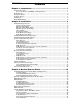
TABLE OF CONTENTS i Contents Chapter 1: Introduction .................................................................. 1 IP-Reach Overview ....................................................................................................................1 Access via Internet, LAN/WAN, or dial-up Modem..............................................................1 Product Photos...........................................................................................................................
ii TABLE OF CONTENTS Remote Serial Control..............................................................................................................35 Physical Connection ..........................................................................................................35 Remote Connection...........................................................................................................35 Changing Serial Settings ..........................................................................
Important Information Login • • • • The default IP-Reach login user name is , with the password . This user has administrative privileges. Passwords are case sensitive and must be entered in the exact case combination in which they were created. The default password must be entered entirely in lowercase letters. To ensure security, change the default password as soon as possible. Default IP Address • IP-Reach ships with the default IP address of 192.168.0.192.
This page intentionally left blank.
CHAPTER 1: INTRODUCTION 1 Chapter 1: Introduction IP-Reach Overview Congratulations on your purchase of IP-Reach, the industry-leading solution for multi-platform, highperformance, network-based, remote KVM console access. IP-Reach enables highly-secure, multi-user, bandwidth-efficient, and software-independent access to your servers’ KVM consoles via a web browser. IP-Reach connects to the keyboard, video, and mouse ports of up to four servers or KVM switches.
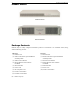
2 IP-REACH USER MANUAL Product Photos IP-Reach M Series IP-Reach TR Series Package Contents IP-Reach ships as a fully configured stand-alone product in a standard 2U 19” rackmount chassis, along with the following contents: TR Series (1) IP-Reach unit (1) IP-Reach TR Series Quick Installation and Setup Guide (1) IP-Reach User Manual (1) Raritan Remote Client software CD-ROM (1) Rackmount Kit (1) Power Cord (1) RJ11 telephone cord (N) CCP20 coaxial cables (N) CCP20F coaxial cables (N = number of ports)
CHAPTER 1: INTRODUCTION 3 Product Features Access • • • • • Remote KVM access via the Internet, LAN/WAN, or dial-up modem Up to four simultaneous user throughput to switch(es) or server(s) Up to 16 simultaneous users (using PC-share mode) Web browser accessible Remote access to serial devices (VT100) connected to IP-Reach serial port Performance • • • • Superior compression algorithm for exceptional performance No impact on target server performance Automatic sensing of video resolution for optimum dis
4 IP-REACH USER MANUAL Terminology This manual makes use of the following terms to indicate components of a typical IP-Reach configuration. While reading the manual, please refer to the diagram below for clarification when necessary. LAN/WAN Target Server(s) Remote PC Local Access Console Local Admin Console Servers to be accessed remotely via IP-Reach and its connected KVM configuration. A Windows-based computer used to access and control target servers connected to IP-Reach.
CHAPTER 2: INSTALLATION 5 Chapter 2: Installation Configuring Target Servers Before installing IP-Reach, first configure any target servers that you wish to access via IP-Reach, in order to ensure optimum performance, as outlined below. Note that the following configuration requirements apply only to target servers, not to the computers that you will be using to access IP-Reach remotely (see Chapter 1: Introduction, Terminology).
6 IP-REACH USER MANUAL Linux Settings On target servers running Linux graphical interfaces, set the mouse acceleration to exactly 1 and set threshold to exactly 1. As mentioned above, please ensure that each target server running Linux is using a resolution supported by IP-Reach at a standard VESA resolution and refresh rate. Each Linux target server should also be set so the blanking times are within +/- 40% of VESA standard values.
CHAPTER 2: INSTALLATION 7 Apple Macintosh Settings For target servers running an Apple Macintosh operating system, while using IP-Reach to access and control your target server, you must set the IP-Reach client (Raritan Remote Client) to “single cursor” mode. Dual cursor mode is not supported, and the two mouse pointers will not appear in sync if you attempt to control a Macintosh server via IP-Reach in dual cursor mode.
8 IP-REACH USER MANUAL TR Series Physical Connections Back Panel of IP-Reach TR Series AC Power Line Attach the included AC power cord to IP-Reach and into an AC Power Outlet. Local Admin Console Attach a PS/2 keyboard and multisync monitor to the indicated ports (see diagram above) in the back of IPReach. Primary Network Port Connect a standard Ethernet cable from the network port to an Ethernet switch, hub, or router.
CHAPTER 2: INSTALLATION 9 Serial Input Port (optional) Serially-controlled devices (VT100 terminal emulation) may be accessed remotely via IP-Reach by attaching them to the Serial IN port found on the back of IP-Reach. The serial port on IP-Reach is of type DTE; when connecting another DTE serial device to IP-Reach, use a null modem serial cable. When connecting a DCE serial device to IP-Reach, use a straightthrough serial cable.
10 IP-REACH USER MANUAL KVM Output / Local Access Console Ports (optional) Connect a PS/2 keyboard, mouse, and multisync monitor to these ports if you want local direct analog access to the servers or KVM switches connected to the corresponding “KVM In” ports. Note: For IP-Reach Model M2, the Local Access Console attached to a KVM Out Port will view the KVM switch or server attached to the corresponding KVM In Port number.
CHAPTER 2: INSTALLATION 11 Initial Configuration During initial configuration, the IP-Reach Setup Wizard helps you quickly set up IP-Reach for the first time. The IP-Reach Setup Wizard appears only when accessing the Administrative Menus on an unconfigured IP-Reach, and guides you through initial configuration parameters. The easiest way to perform this initial configuration is by using the Local Admin Console (see ‘Physical Connection’ instructions in the previous sections). 1.
12 IP-REACH USER MANUAL - Line Speed & Duplex: Enter the visual efficiency for the monitor: Auto detect 10 Mbps/Full Duplex, 10 Mbps/Half Duplex, 100 Mbps/Full Duplex, or 100 Mbps/Half Duplex Obtain IP address automatically (DHCP): ♦ YES: Enables dynamic IP addressing for IP-Reach. Each time IP-Reach boots, it requests an IP address from the local DHCP server.
CHAPTER 2: INSTALLATION 13 Connect to IP-Reach Remotely Having completed the physical installation of IP-Reach, you are now ready to establish an initial network connection. Below are basic instructions for doing so. Please see Chapter 3: Raritan Remote Client for detailed instructions, being sure to review the “KVM Session Properties” and “Color Calibration” sections to optimize your IP-Reach performance. Launch Raritan Remote Client (RRC) 1.
14 IP-REACH USER MANUAL Establish a Connection Upon launching the Raritan Remote Client (RRC), IP-Reach will request your user credentials. Log on with the default username and password ( and ). You will connect to your IP-Reach unit. Use the RRC Navigator, found on the left-hand side of the RRC window, to select and connect to a port. Click on “Synchronize Mouse” to converge the mouse pointers displayed. The RRC Navigator displays any known Raritan networked appliances.
CHAPTER 3: RARITAN REMOTE CLIENT (RRC) 15 Chapter 3: Raritan Remote Client Invoking Raritan Remote Client (RRC) via Web Browser IP-Reach features Web Browser access, providing a connection from any Windows-based Remote PC running Microsoft Internet Explorer 4.0+, Mozilla 1.1+, and Netscape 7+.
16 IP-REACH USER MANUAL 3. Depending on your browser’s security configuration, you may see any or all of the following dialog boxes, confirming the access and launch of an externally-provided program. Click [Yes] to advance through any of these prompts. Note: Microsoft Windows 2000 and Microsoft Windows XP restrict certain types of users from downloading and running ActiveX controls and plug-ins, regardless of the settings in Internet Explorer and regardless of your approval of the above warnings.
CHAPTER 3: RARITAN REMOTE CLIENT (RRC) 17 Optional: Installing Raritan Remote Client Software Note: This step is optional. IP-Reach can be accessed from a Remote PC either by installing RRC software, or by launching RRC via web browser (see previous section). Accessing IP-Reach via web browser does not require any software installation on the Remote PC. 1. 2. 3. Insert the provided RRC CD-ROM into the CD-ROM drive of your PC. The RRC setup program will run automatically.
18 IP-REACH USER MANUAL RRC Window Layout Raritan Remote Client functions are grouped into five general sections on the screen. Each section will be discussed in detail further in this chapter.
CHAPTER 3: RARITAN REMOTE CLIENT (RRC) 19 RRC Navigator The RRC Navigator provides a single view to every known Raritan device, allowing convenient access to multiple Raritan networked appliances. The RRC Navigator displays: • All Raritan devices for which a connection profile exists • All Raritan devices that are automatically identified on the network Note: Automatic Raritan device identification uses UDP protocol, and will usually identify all Raritan devices on your subnet.
20 IP-REACH USER MANUAL Navigator Options Certain RRC Navigator attributes may be customized to your preferences. Display / Hide Navigator – Toggle whether the RRC Navigator is shown. This option can also be toggled by choosing View → Navigator from the Menu Bar. Refresh Navigator – Update the device status information shown in the RRC Navigator.
CHAPTER 3: RARITAN REMOTE CLIENT (RRC) 21 For a TCP/IP Connection, select how RRC should locate your Raritan device: • IP Address: The IP address assigned to your Raritan device (see Chapter 4: Administrative Functions, Network Configuration). • Name: The name assigned to your Raritan device during initial setup (see Chapter 4: Administrative Functions, Network Configuration). Note: If dynamic DHCP addressing is used for IP-Reach, use “Find IP-Reach by Name.
22 IP-REACH USER MANUAL Establishing a New Connection To connect to a Raritan networked device, simply double-click on its entry in the RRC Navigator. You will be asked to authenticate the device. Note: The default IP-Reach login user name is , with the password . This user has administrative privileges. Passwords are case sensitive and must be entered in the exact case combination in which they were created. The default password must be entered entirely in lowercase letters.
CHAPTER 3: RARITAN REMOTE CLIENT (RRC) 23 RRC Toolbar and Shortcuts Raritan Remote Client Toolbar The RRC Toolbar provides convenient, one-click access to the most commonly used features and parameters of Raritan Remote Client: BUTTON BUTTON NAME HOTKEY FUNCTION New Profile Disconnects the Remote PC from IP-Reach, ending a remote communication session.
24 IP-REACH USER MANUAL RRC Status Bar The Status Bar at the bottom of the Raritan Remote Client window conveys information about the status of your remote connection session to IP-Reach. Video Sensing Status / Path Indicator Indicates the occurrence of video sensing. Bandwidth Usage Indicator Indicates how much of your total available bandwidth is currently being used. The Connection Speed setting, found under the Compression tab of the Connection Properties screen, determines total available bandwidth.
CHAPTER 3: RARITAN REMOTE CLIENT (RRC) 25 Remote KVM Console Control After using the RRC Navigator to establish a connection with an IP-Reach unit (see the previous section: Establishing a Connection), the Navigator entry corresponding to the IP-Reach unit will expand to show all ports on the IP-Reach enabled for remote access. To establish a remote KVM console connection, simply double-click on the KVM path that you would like to control.
26 IP-REACH USER MANUAL Single Mouse Mode / Dual Mouse Mode When remotely viewing a Target Server that uses a pointing device, by default you will see two mouse pointers within the Remote Desktop area of the Raritan Remote Client window. The Raritan Remote Client mouse pointer, generated by the operating system on which RRC is running, slightly leads the Target Server's mouse pointer during movement, a necessary result of digital delay.
CHAPTER 3: RARITAN REMOTE CLIENT (RRC) 27 Selecting Servers with a KVM Switch Two buttons allow users single-click access to the On Screen User Interface (OSUI) provided by your KVM Switch. The [Enter OSUI] and [Exit OSUI] buttons on the RRC toolbar have been provided to simplify the use of IP-Reach in conjunction with KVM Switches. Enter OSUI Exit OSUI The steps below configure RRC to properly interoperate with your KVM switches to enter and exit their user interfaces.
28 IP-REACH USER MANUAL Keyboard Macros RRC allows users to create custom keyboard macros in order to send given key sequences to the remote server or KVM switch connected to IP-Reach. This feature allows customers to send keystrokes to remote servers that may be otherwise unintentionally interpreted by the computer on which RRC is running.
CHAPTER 3: RARITAN REMOTE CLIENT (RRC) 29 3. The Add Keyboard Macro dialog box opens. 4. Build the Keyboard Macro by editing all the fields in the Add Keyboard Macro window, in the order described below. Click [OK] when finished. a. Enter a name into the Keyboard Macro Name field, which will appear on the RRC Menu Bar, after successful creation of the keyboard macro. For our example, "Minimize All Windows". b.
30 IP-REACH USER MANUAL 5. After clicking [OK], the Keyboard Macros dialog box will appear, listing your new keyboard macro. 6. Click [Close] to complete the keyboard macro editing procedure. Running a Keyboard Macro Once a macro is created, it can be run via the RRC Menu Bar or with the hotkey combination if one had been designated during the macro creation. Menu Bar Activation After a macro has been created, it appears in the Keyboard menu on the RRC Menu Bar.
CHAPTER 3: RARITAN REMOTE CLIENT (RRC) 31 Connection and Video Properties IP-Reach's dynamic video compression algorithms maintain KVM console usability under varying bandwidth constraints. Unlike competitive solutions, IP-Reach optimizes its KVM output for not only LAN utilization, but also via the WAN and dial-up. By dynamically adjusting color depth and limiting video output, IP-Reach offers the optimal balance between video quality and system responsiveness in any bandwidth constraint.
32 IP-REACH USER MANUAL Internet Flow Control Many public WAN links are by their very nature unpredictable. Packets sent over the public Internet do not necessarily arrive at their destination in the order they were sent. When using IP-Reach over an unpredictable public WAN (particularly in international scenarios), the Internet Flow Control toggle ensures that packets transmitted by IP-Reach are received and reconstructed by RRC in the correct order.
CHAPTER 3: RARITAN REMOTE CLIENT (RRC) 33 Analog-to-Digital Settings The following parameters are best left to IP-Reach to automatically detect (on the RRC Menu Bar, select Video > Auto-sense Video Settings), but a brief description of each is included here. • PLL Settings: If the video image looks extremely blurry or unfocused, the PLL Settings for clock and phase can be adjusted until a better image appears on the active Target Server. - Clock: Horizontal sync divider to produce pixel clock.
34 IP-REACH USER MANUAL Color Calibration Automatic Color Calibration adjusts the color settings on IP-Reach to reduce excess color noise and data during digitization of video images. This data streamlining will increase the operational performance of IPReach, particular color accuracy. A very simple procedure to execute, Color Calibration should be performed if the color levels (hue, brightness, saturation) of transmitted video images do not seem accurate.
CHAPTER 3: RARITAN REMOTE CLIENT (RRC) 35 Remote Serial Control In addition to remote KVM console access, IP-Reach also offers users the convenience of accessing a serial console via web browser as well. Any serial console supporting VT100 emulation may be connected to the SERIAL IN port found on the back panel of IP-Reach, and accessed using the Raritan Remote Client. Physical Connection The SERIAL IN port found on the back panel of IP-Reach is a DB9 Male connector, with a standard RS232 DTE pin-out.
36 IP-REACH USER MANUAL Changing Serial Settings You may change the serial terminal settings such as baud rate, parity, and stop bits used by IP-Reach to communicate with your serial device, by right-clicking on the serial port entry in the RRC Navigator, and selecting Serial Parameters in the menu. Click [OK] when finished.
CHAPTER 3: RARITAN REMOTE CLIENT (RRC) 37 Log Files IP-Reach provides detailed activity logs for troubleshooting purposes, which may be downloaded to your local computer for viewing, reporting, and analysis. On the RRC Menu Bar, select Tools → Save Activity Log, or Tools → Save Diagnostic Log.
38 IP-REACH USER MANUAL
CHAPTER 4: ADMINISTRATIVE FUNCTIONS 39 Chapter 4: Administrative Functions Accessing the Administrative Functions Access and execute Administrative functions via local admin console, or via remote administration. Only administrators (users with administrative privileges) can access the IP-Reach Administrative Menus. Local Admin Console Power ON the IP-Reach unit via the power switch on the back of the unit. Note: The default IP-Reach login user name is , with the password .
40 IP-REACH USER MANUAL Remote Admin Console An alternative way to access IP-Reach’s administrative functions is to do so remotely, using the Raritan Remote Client. Any administrative user logged on to IP-Reach at a Remote PC can perform administrative functions remotely to make changes to the system, as long as IP-Reach is set to allow remote administration privileges – see Allow Remote Administration on the Security Configuration screen.
CHAPTER 4: ADMINISTRATIVE FUNCTIONS 41 Network Configuration After making changes to the Network Configuration, press to save. You must reboot when all changes are complete in order to apply them. • Name: Designate a unique name for this IP-Reach unit, for example, “Miami Data Center.” The default name is IP-Reach. • Enable Ethernet Interface: Designates whether IP-Reach should enable its Ethernet adapter as active (default: YES).
42 • IP-REACH USER MANUAL Enable IP Failover (TR Series only): This setting, which appears only for TR Series models, enables the secondary Ethernet port to be active for failover utilization. - When enabled, IP-Reach will verify the availability of its primary Ethernet port at a constant interval indicated by the Ping Interval in seconds setting.
CHAPTER 4: ADMINISTRATIVE FUNCTIONS 43 Two Paths – Two Ports Each: Used when IP-Reach is connected to two KVM switch configurations. There are two main paths, one to each KVM configuration. Users must select the Path (or KVM configuration) they wish to access upon IPReach login. Up to two users can connected to each KVM configuration. IP-Reach will automatically assign the next open channel on the selected path to each user.
44 IP-REACH USER MANUAL Three Paths – Two Ports, One Port, One Port (2, 1, 1) : Used when IP-Reach is connected to three KVM switch configurations. There are three main paths, one to each KVM configuration. Users must select the Path (or KVM configuration) they wish to access upon IPReach login. Up to two users can connect to the first Path (KVM configuration) and IP-Reach will automatically assign the next open channel on the selected path to each user.
CHAPTER 4: ADMINISTRATIVE FUNCTIONS 45 Security Configuration • Encryption mode: Toggle through the choices and select the desired level of encryption for initial connection authentication and remote session video data transfer. - No encryption: No encryption or security. Neither the initial connection authentication nor remote video data transfer is encrypted. - SSL authentication, NO data encryption: This mode secures user names and passwords, but not KVM data.
46 • IP-REACH USER MANUAL PC Share Mode: Determines global concurrent remote access. Enables up to eight remote users to simultaneously log on to one IP-Reach unit and concurrently view and control a Target Server through IP-Reach. Control is based on first active/keyboard mouse input, so multiple remote users attempting keyboard input or mouse movement at exactly the same moment may experience uneven control. - Private Mode (default): No PC Share.
CHAPTER 4: ADMINISTRATIVE FUNCTIONS • 47 Private key: Enter a private key password. This private key acts as a second level of password protection. Only remote users who know the private key password, in addition to their user name and password, can log in and connect to IP-Reach. - Confirm private key: Enter private key password again for re-confirmation. Note: Private key passwords are case sensitive.
48 IP-REACH USER MANUAL - No Limit (default): Each active user can consume as much bandwidth as needed. 10, 5, 2, or 1 megabit or 512, 256, 128 kilobit: Bandwidth consumed by each active user during the operation of this IP-Reach unit is limited to the selected quantity. The lower the bandwidth allowed, the slower the performance that may result. Press to save changes or to cancel changes, and return to Configuration Menu.
CHAPTER 4: ADMINISTRATIVE FUNCTIONS 49 Create or Change Group Accounts 1. At the Main Menu, type to add or change a Group Account. 2. The Group Account screen appears. a. To add a new group account, type the letter . b. To change group account properties, use the key to move through the list and press to select a group to change.
50 IP-REACH USER MANUAL 3. The Group Account Settings screen appears. a. Type the Group Account name in the Group Name field. The name can consist of alpha-numeric characters, up to 23 characters long, and the first character cannot be a number. b. Use the <Ç> and <È> arrow keys or the key to move through the line items, and press the to toggle choices from YES to NO. When finished, press + to save your data, press to exit the screen without saving. 4.
CHAPTER 4: ADMINISTRATIVE FUNCTIONS 51 5. Your changes are not yet saved. You will be returned to the Group Account Settings screen for the user group you are editing or creating. 6. You must press + once more while in this screen to save the permissions settings to your given user group. Delete Group Accounts To delete an existing group account, type at the Main Menu, and when the Group Account screen appears, press to select the group account to delete, and then press .
52 IP-REACH USER MANUAL Create or Change User Accounts 1. At the Main Menu, type to add or change a user account. 2. The User Account window appears. a. To add a new user account, type the letter . b. To change a user account properties, use the key to move through the list and press to select a user to change. 3. The User Account Settings screen appears. a. Type the user’s name in the User Name field.
CHAPTER 4: ADMINISTRATIVE FUNCTIONS 4. 53 Press + to return to the Main Menu. Delete User Accounts To delete an existing user account, type at the Main Menu, and when the User Account screen appears, press to select the user account to delete, and then press . Please note that you cannot delete the default user, ADMIN.
54 IP-REACH USER MANUAL Remote Authentication Implementation Introduction Note to CommandCenter Users If you plan to configure IP-Reach to be integrated with and controlled by Raritan’s CommandCenter management appliance, this section of the User Manual does not apply to you. When an IP-Reach unit is controlled by CommandCenter, CommandCenter determines the allowed users and groups. Please refer to your CommandCenter User Guide.
CHAPTER 4: ADMINISTRATIVE FUNCTIONS 55 Authentication vs. Authorization When your IP-Reach unit is configured for remote authentication, the external authentication server is used primarily for the purposes of authentication, not authorization. Authorization is determined by IP-Reach on the basis of user groups.
56 IP-REACH USER MANUAL General Settings for Remote Authentication You must log on to IP-Reach as default Administrator (user name , password ) to set Remote Authentication properties. 1. At the Main Menu, press the letter to Configure IP-Reach. 2. When the Configuration Menu appears, press to configure Remote Authentication. The Authentication and Accounting screen appears. 3.
CHAPTER 4: ADMINISTRATIVE FUNCTIONS b. 57 Type the server secret needed to authenticate against your remote authentication servers in the Server Secret field. Re-type the server secret in the Confirm Secret field. c. Type the time of inactivity (in seconds) that should pass before the server times out in the Server Timeout (seconds) field. d. Type the IP addresses of your primary and secondary remote authentication servers in the Primary Server IP and Secondary Server IP fields. 5.
58 IP-REACH USER MANUAL 6. If you are appointing Remote Accounting, in the Authentication and Accounting screen, to the Enable Remote Accounting field, and press to toggle to RADIUS. 7. When finished, press to save your changes, or press to exit without saving Remote Authentication configurations. Implementing LDAP Remote Authentication Reminder: Microsoft Active Directory functions natively as an LDAP authentication server.
CHAPTER 4: ADMINISTRATIVE FUNCTIONS 59 Returning User Group Information via RADIUS When a RADIUS authentication attempt succeeds, IP-Reach determines the permissions for a given user based on the permissions of the user’s group. Your remote RADIUS server can provide these user group names by returning an attribute, implemented as a RADIUS FILTER-ID. The FILTER-ID should be formatted as follows: Raritan:G{GROUP_NAME} where GROUP_NAME is a string, denoting the name of the group to which the user belongs.
60 IP-REACH USER MANUAL Time and Date Current Date and Time on the IP-Reach unit are listed on this screen. Once saved, Time and Date changes will not take effect until IP-Reach is restarted. • New Date / New Time: To manually input changes to current date and time values. • Adjust for daylight savings time: Toggle between YES and NO to reflect whether your country or state follows the daylight savings time procedure.
CHAPTER 4: ADMINISTRATIVE FUNCTIONS 61 View IP-Reach Status The IP-Reach Event Log screen shows a log file containing information about IP-Reach log in and connection activities.
62 IP-REACH USER MANUAL Diagnostics While navigating the Main Menu of the Administrative Console, pressing and will invoke the IP-Reach Diagnostic functions. These functions are meant to enable Raritan Technical Support to assist you in the case of a problem with your IP-Reach unit. Do not invoke these functions unless you are fully aware of their meanings and intended use. Please contact Raritan Technical Support should you require more information.
APPENDIX A: SPECIFICATIONS 63 Appendix A: Specifications ITEM DIMENSIONS (WXDXH) WEIGHT POWER IPR-TR361 2U 19” Rackmount Case: 19” (W) x 21.25” (D) x 3.5” (H) 482 mm (W) x 540 mm (D) x 89 mm (H) 28.2lbs. (12.79kg.) 110/220V auto-switching (50/60 Hz European) IPR-TR362 2U 19” Rackmount Case: 19” (W) x 21.25” (D) x 3.5” (H) 482 mm (W) x 540 mm (D) x 89 mm (H) 28.6lbs. (12.97kg.) 110/220V auto-switching (50/60 Hz European) IPR-TR364 2U 19” Rackmount Case: 19” (W) x 21.25” (D) x 3.
64 IP-REACH USER MANUAL Cable Specifications Standard RJ11 based phone cord to connect modem to a phone line (provided)** Category 5e UTP cable to connect to network **TR Series only KVM Switch Specifications Supports KVM switches utilizing an On-Screen User Interface, including Raritan’s Paragon, Z-Series, MasterConsole MX4, and MasterConsole II product lines.
APPENDIX B: SNMP FEATURES 65 Appendix B: SNMP Features For convenient monitoring with standard network management systems such as HP OpenView or IBM Tivoli software solutions, IP-Reach features an SNMP agent with standard MIB2 support. IP-Reach responds to SNMP GET requests with standard MIB2 variables, although for security reasons only a subset of the variables are provided.
66 IP-REACH USER MANUAL
APPENDIX C: FREQUENTLY ASKED QUESTIONS 67 Appendix C: Frequently Asked Questions QUESTION: ANSWER: What is IP-Reach? IP-Reach is the easiest, fastest, most reliable way to remotely access and manage multiple servers connected to a Raritan KVM Switch - no matter where you are or where your servers are located. How does IP-Reach work? IP-Reach connects to the keyboard, video, and mouse ports of a server or KVM switch.
68 IP-REACH USER MANUAL QUESTION: ANSWER: How Is IP-Reach administration carried out? Administrators access IP-Reach through a connected IP-Reach Admin Console. A simple keyboard driven interface of menus offers straightforward access to IP-Reach setup and control. User profiles, security settings, configuration and diagnostics are just a few of the options available.
APPENDIX D: TROUBLESHOOTING 69 Appendix D: Troubleshooting Problems and Suggested Solutions REMOTE CONNECTION PROBLEMS SOLUTION I cannot connect to IP-Reach via dial up modem. Ensure that you have specified the modem device for your Remote PC in the Add Connection Window (Dial-up type connection) modem field.
70 IP-REACH USER MANUAL DIRECT ANALOG USER CONSOLE PROBLEMS from a Direct Analog User Console. SOLUTION users are currently attempting to control the active Target Server. I cannot view the Target Server that I am looking for from a Direct Analog User Console. Ensure that you are looking at the Direct Analog User Console connected to the correct User Port. Remember, Direct Analog User Consoles can be attached to User Ports 1 through 4. Each User Console will view the path of the matching KVM Port.
APPENDIX D: TROUBLESHOOTING 71 KVM ON-SCREEN USER INTERFACE (OSUI) PROBLEMS SOLUTION Clicking on the Enter On-Screen Menu button does not bring up the connected KVM switch’s On-Screen User Interface (OSUI). Nothing happens. IP-Reach may not be set to the correct KVM switch Hotkey activator. The default Hotkey setting is or Scroll Lock+Scroll Lock in the IP-Reach Options window.
72 IP-REACH USER MANUAL MOUSE PROBLEMS SOLUTIONS The larger IP-Reach Mouse Pointer does not track or is not in sync (not aligned) with the smaller Target Server Mouse Pointer. Click Synchronize Mouse, or press . Ensure each Target Server uses a standard Windows mouse driver. For Windows 2000 based Target Servers, set the mouse motion speed on each Target Server to the middle speed setting between Slow and Fast and the mouse motion acceleration speed on each Target Server to .
APPENDIX D: TROUBLESHOOTING 73 IP-REACH PROBLEMS SOLUTION There is no control and no frame grabbing activity occurring. IP-Reach seems to have locked-up. An internal serial data cable, which connects the frame grabber card to the motherboard of IP-Reach, may have become disconnected. Contact Raritan Technical Support for assistance. I cannot power down IP-Reach. The main power switch for IP-Reach is on the back of the unit. To turn off IP-Reach hold the power key down for a few seconds.
74 IP-REACH USER MANUAL Event Log File and On-Screen Error Codes IP-Reach will display or log an error code in the IP-Reach Event Log Screen in the event of a problem occurring. Error codes are eight-digit hexadecimal numbers, containing two parts: the first four denote error type; and the second four digits denote a location code. These last four digits of the IP-Reach error code are the most useful in determining what has caused a system failure.
APPENDIX D: TROUBLESHOOTING ERROR CODE (LAST 4 DIGITS) 75 MEANING RECOMMENDATION 0011 The Ethernet controller could not be found. There is a problem with the IP-Reach hardware. 0012 The modem could not be found. Power off the system and make sure the frame grabber card is inserted firmly. If the problem persists, there may be a problem with your IP-Reach hardware. 0013 Memory allocation error. Reboot IP-Reach. Make sure the BIOS memory test recognizes at least 64MB of RAM.
76 ERROR CODE (LAST 4 DIGITS) IP-REACH USER MANUAL MEANING RECOMMENDATION Recovery CD-ROM. 0024 SSL read failed. Reboot IP-Reach. Make sure the BIOS memory test recognizes at least 64MB of RAM. If the problem persists, restore the software and file system from the Recovery CD-ROM. 0025 Memory allocation error. Reboot IP-Reach. Make sure the BIOS memory test recognizes at least 64MB of RAM. If the problem persists, restore the software and file system from the Recovery CD-ROM.