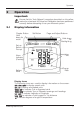
Dual Digital Display
mn100 Dual Digital Display EMC Conformance All Raymarine equipment is designed to the best industry standards for use in the recreational marine environment. The design and manufacture of Raymarine equipment conforms to the appropriate Electromagnetic Compatibility (EMC) standards. Correct installation is required to ensure that performance is not compromised. Important Due to the wireless communication systems used in Micronet instruments they are only recommended for use on boats up to 18 metres (60 ft.
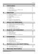
Contents 1 2 Information Page 1.1 1.2 1.3 1.4 2 2 2 4 Operation 2.1 2.2 2.3 2.4 2.5 2.6 2.7 3 Entering Setup and Calibration Mode Chapter and Page Setup and Calibration Editing Values Setup Page Description Calibration Page Description - Depth Offset Speed Calibration Wind Calibration Compass Calibration and Alignment - Tools List & PartsPrecautions and Positioning Advise Bracket Mounting Surface Mounting External Power Connections - 29 30 31 32 33 33 34 35 36 Maintenance and Fault Finding 6.
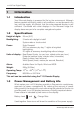
mn100 Dual Digital Display 1 Information 1.1 Introduction Your Micronet display is powered for life by the environment. Although feature packed and highly visible in all conditions, current demand is so low, and the supply so efficient, that the solar-powered display is self sufficient. Combined with other displays in the Micronet range this display becomes part of a complete navigational system. 1.2 Specifications Height of digits: 20mm (0.
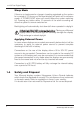
Information Bright Sunny Day Battery is charged and being topped up by the sun. (see Note) Battery is low and being charged by the sun. Overcast Day Battery is charged and requires no further charging. Battery is low but maintaining it’s level. Night Battery is charged but is not charging. Battery is low with no charging. LOW Power It is recommended that the instrument be left in daylight for some time for the battery to recover, or charge from an external 9-30V power source.
mn100 Dual Digital Display Sleep Mode If there is no boat speed or change in heading registered on the system for a period of 12 hours your Micronet display will switch off to conserve power. A "POWER SAVE" alarm will sound before the system switches off. Pressing any button within 10 seconds of the alarm sounding will allow the system to remain switched on. Backlighting will automatically shut down/off when operated in daylight. Artificial light WILL NOT recharge the battery.
Operation 2 Operation Important: Ensure that the "Auto Network" procedure described on the yellow instruction sheet and full Setup and Calibration has been performed correctly before attempting to use your Micronet system. 2.
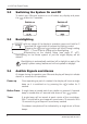
mn100 Dual Digital Display 2.2 Switching the System On and Off To switch your Micronet system on or off select any display and press the button for 2 seconds. Switch on 2.3 Switch off Backlighting At any stage of the display’s operation press and hold for 2 seconds the button to access the lighting control. Pressing the and buttons will scroll through setting OFF, 1, 2 and 3 whilst changing the Backlighting.
Operation Alarm Continuous bursts of three beeps will indicate an alarm. The alarm activated will be indicated on the digital display, accompanied by the flashing symbol. Pressing any button will silence the alarm. See fault finding section on p37. Depth Shallow Alarm The water depth has fallen below the preset alarm level. The depth value that triggers the alarm is affected by any keel or waterline offsets that have been added. See page 22 s11 to set the alarm function.
mn100 Dual Digital Display 2.5 Utilities Keylock The Keylock feature protects from accidental key presses and is intended for use in high activity applications such as crewed race yachts.
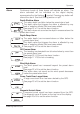
Operation 2.6 Chapter and Page Operation Information is displayed in a “Chapter and Page” format using the (Chapter) button to scroll through the Chapters which are displayed in the upper part of the window and the and (Page) buttons to move between Pages within a Chapter which are displayed in the lower part of the window. Chapter Sequence Shown in Upper Window (for a full description of each Chapter see page 11 - c1 to c8) www.raymarine.
mn100 Dual Digital Display It is possible to select any Page (lower window) within any Chapter (upper window) giving you a chance to display any two pieces of information available at any time. Once a Page display has been selected within a Chapter the same Page will be displayed every rollover of the Chapter sequence ensuring that you return to your choice of display within a maximum of 8 presses of the (Chapter) button.
Operation 2.7 Chapter and Page Descriptions Chapters C1 Depth The Actual Depth beneath the vessel as measured by the Depth Transducer. The displayed value will be affected by any keel or waterline offset added (see page 29). C2 Apparent Wind Speed The actual Wind Speed with respect to the vessel as measured by the Wind Transmitter. C3 Boat Speed The vessels actual speed through the water as measured by the Speed Transducer.
mn100 Dual Digital Display Pages P1 Boat Speed The vessels Actual Speed through the water as measured by the Speed Transducer. P2 Velocity Made Good to windward The vessels calculated Speed Directly Upwind. This value is calculated by the display from the Boat Speed and True Wind Angle. P3 Velocity Made Good to waypoint The vessels calculated Speed directly towards the active Waypoint. This value is calculated by the GPS Antenna.
Operation P10 Maximum Depth (identified by displayed FT/M/FTM icon) The Maximum Depth encountered since switch on or since the last Maximum Depth Reset. To Reset see page 20 -s3. P11 Apparent Wind Speed (identified by displayed KTS/M icon) The Actual Wind Speed with respect to the vessel as measured by the Wind Transmitter. P12 Apparent Wind Angle The actual Wind Angle with respect to the vessel as measured by the Wind Transmitter.
mn100 Dual Digital Display P17 Wind Shift, Head or Lift Indicates changes in the wind against a compass heading. Spotting these wind changes is the key to fast sailing upwind. The system automatically detects the mean wind direction by averaging over a time period of 2 minutes to 60 minutes (this time period can be changed in setup). However, to manually overide this automatic calculation and set the mean wind direction: 1.
Operation P22 Latitude Vessels current Latitude as calculated by the GPS Antenna. P23 Longitude Vessels current Longitude as calculated by the GPS Antenna. P24 Bearing to Waypoint Bearing To (active) Waypoint. The active Waypoint being the one to which the GPS is currently navigating. P25 Distance to Waypoint Distance To (active) Waypoint. The active Waypoint being the one to which the GPS is currently navigating.
mn100 Dual Digital Display P29 Timer Countdown or elapsed time stopwatch. Press and hold for 1 second the button and use the and buttons to set the required countdown time in minutes. Press the button quicklyto prepare to start the countdown. Press the button quickly to start the countdown. The display will sound a single beep each 60 seconds until 1 minute remains when a beep will sound at 10 second intervals.
Operation P30 Time Current Time as received from the GPS Antenna corrected to local time if an offset has been added (see page 26 -s36). P31 Date Current date as received by the GPS Antenna. P32 Volts The voltage connected to the PWR input of the hull transmitter or the Wireless (NMEA) Interface. P33 Lock Produces a “Trim” indication showing an increase or decrease in value from a set point. Select the appropriate chapter in the upper display using the button.
mn100 Dual Digital Display 3 Setup and Calibration 3.1 Entering Setup and Calibration Mode To enter the Setup and Calibration menu press and hold for 2 seconds the button. This will not work when in the Race Timer page. 3.2 Chapter and Page Setup and Calibration Setup and Calibration is displayed in a “Chapter and Page” format using the button to scroll through the Chapters and the and buttons to move between Pages. The diagram below shows the information format.
Set-up and Calibration Setup and Calibration - Chapter and Page layout Chapters Pages SETUP TRIP MEMRY DEPTH DEPTH MIN MAX SPEED MAX SETUP SPEED DEPTH WIND UNITS UNITS S6 UNITS S7 UNITS S8 SETUP DEPTH DEPTH ALARM SHALL S11 DEEP S12 AVG S3 S2 S1 SPEED LOG OFF TEMP UNITS UNITS S9 WIND CRSE S13 S5 S4 S10 XTE HIGH S14 LARGE S15 WP ARRVE S16 SETUP SPEED RESP SPEED S18 S17 SETUP DEPTH SETUP WIND CMPAS OPTS RESP WND Wnd +/- nnn S23 S20 WIND +/- n% S24 RESP H
mn100 Dual Digital Display 3.4 Setup Page Description SETUP MEMRY - Memory Chapter In each case press the button quickly to reset. S1 Trip Distance The Distance Travelled since the last Trip Reset. Resets to 0.00. S2 Depth Minimum The Minimum Depth encountered since switch on or since the last Minimum Depth Reset. Resets to Current Depth. S3 Depth Maximum The Maximum Depth encountered since switch on or since the last Maximum Depth Reset. Resets to Current Depth.
Set-up and Calibration SETUP UNITS - Units Chapter In each case press the button quickly to edit, press the or button to change units and press the button quickly to select the chosen units. Default values are indicated in bold. S6 Speed The units in which ALL speed related information is displayed. The options available are: Knots (KTS), Kilometres per hour (KPH) or Statute Miles per hour (MPH). S7 Depth The units in which ALL depth related information is displayed.
mn100 Dual Digital Display SETUP ALARM - Alarms Chapter In each case press the button quickly to edit, press the or to change values and press the button quickly to save the entered value. In the case of On/Off selection the button will toggle the setting On and Off. Default values are indicated in bold. S11 Shallow Water Alarm Sets the Shallow Depth at which the display will alarm. The options are: OFF and 0.0 to 25 feet (0.0 to 7.6 metres) (0.0 to 4.1 fathoms).
Set-up and Calibration S15 Cross Track Error Alarm Sets the display to alarm if a Large Cross Track Error alarm is issued by the GPS. The options are: On/Off. S16 Waypoint Arrival Alarm Sets the display to alarm if a Waypoint Arrival alarm is issued by the GPS. The options are: On/Off. 3.5 Calibration Page Description In each case press the button quickly to edit, press the or button to change units and press the button quickly to select the chosen units. Default values are indicated in bold.
mn100 Dual Digital Display S20 Sea Temperature Calibration The sea temperature calibration factor adds a value which corrects the information from the temperature sensor and ensures the water temperature is displayed correctly. SETUP DEPTH - Depth Chapter S21 Keel/Waterline Offset Allows a keel offset to be added allowing the display depth reading to indicate depth below the bottom of the boat, or a waterline offset allowing the depth reading to indicate actual water depth.
Set-up and Calibration SETUP CMPAS - Compass Chapter S26 Heading Response Sets the update period of the Compass display. Auto/Slow/Medium/Fast S27 Heading Format Tells the system to show heading information in either Magnetic or True format. S28 Compass Heading Aligns the displayed heading with the Actual Magnetic Heading of the boat. See page 32 for the calibration process. S29 Magnetic Variation Allows manual entry of local magnetic variation.
mn100 Dual Digital Display SETUP OPTS - Options Chapter S31 Auto Networking Only available on the display which was used to power up the system. Refer to the "Auto Network" sheet for further information. S32 Key Lock Enables the key locking feature. See page 8 section 2.5 for the key locking process. S33 Page Hiding Enables the user to hide pages. Refer to page 8, section 2.5. See page 8 section 2.5 for the page hiding process. S34 Pages Hidden/Unhide Pages Displays the number of hidden pages.
Set-up and Calibration S37 Light Tells the display to control the system Backlighting or just its own Backlighting. The options are: Network/Local. S38 LCD Contrast Allows the contrast of the LCD display to be adjusted to suit the viewing angle of the display. The lower the figure the less contrast is visible. The available options are: 1 - 7 default 4. S39 Boat Show Allows the display to show information when NOT installed as part of a Micronet system for demonstration purposes only.
mn100 Dual Digital Display S42 Hull Transmitter Signal Strength Shows the software version (upper display), signal strength and battery condition (level and charge rate) of the Hull Transmitter to assist in trouble shooting and fault finding. S43 Wind Transmitter Signal Strength As above but for Wind Transmitter information. S44 Wireless (NMEA) Interface Signal Strength As above but for Wireless (NMEA) Interface information.
Seatrial and Calibration 4 Seatrial and Calibration Once the Micronet display system has been installed on the vessel and Auto Networking has been completed it is necessary to carry out Calibration. It is not safe to use the instruments for navigational purposes until Calibration has been carried out correctly. 4.1 Depth Offset The default depth offset is -3.5 feet (a keel offset of 3.5 feet).
mn100 Dual Digital Display 4.2 Speed Calibration To ensure that the Boat Speed (and Distance) is accurate it is necessary to calibrate the speed to take into account variations in water flow between different hulls. Adjustment is made by multiplying the Speed through the Water (V) by a percentage Calibration Factor. It is essential to carry out this procedure at a time where little or no tide is flowing.
Setrial and Calibration 4.3 Wind Calibration Both Wind Speed and Direction can be calibrated to ensure that readings from the Wind Transmitter are displayed accurately. Wind Angle Offset Motor the vessel directly into the wind. Press and hold the button for 2 seconds to enter Setup Press the button repeatedly to scroll to the SETUP WIND chapter Press the button to advance to the Wind Angle page Press the button to enter Edit Mode Press the and buttons to change the displayed value to 000.
mn100 Dual Digital Display 4.4 Compass Calibration and Alignment To ensure that inaccuracies caused by metallic and magnetic objects on the boat are kept to a minimum is necessary to calibrate the compass. A deviation caused by surrounding objects will be compensated for and the compass reading may be set to the correct heading.
Set-up and Calibration 5 Installation 5.1 Tools list and Parts Tools Required 2.5mm or 5mm Drill Bit (7mm if power connection required) Power Drill Cross Head Screwdriver Parts List 5.2 Mounting Template Display Backplate and 2x Clip Brackets Mounting Screws (3) Mounting Bolts (3) M4 Studs & Thumbnuts (3) Sealing Gaskets (4) Double Sided Tape Precautions and Positioning Advice Ensure mounting surface is flat. Leave space between displays for sun covers.
mn100 Dual Digital Display 5.3 Bracket Mounting (Preferred Method) This method allows for the easy removal of a display as and when required, for either security reasons or to prevent damage or discomfort whilst not in use. 1. Using the three supplied M4 bolts attach the back plate to the rear of the display (Fig.1). 2. Drill three 2.5mm holes marked "A" on the Template and using the supplied self tapping screws, screw the clip bracket to the mounting surface (Fig.2). 3.
Installation 5.4 Surface Mounting Where there is no access to the rear of the mounting surface Easy installation but will allow removal without gaining access to the boat. Position the supplied Template carefully before starting. 1. Drill three 2.5mm holes marked "B" on the Template. 2. Carefully snap the facia of the display off the main body taking care not to drop the button pads. .
mn100 Dual Digital Display Where access is available to the rear of the mounting surface This method allows for maximum security of a permanently mounted display. Position the supplied Template carefully before starting. 1. 2 3. 4. Drill three 5mm holes marked "B" on the Template. Stick the 3 supplied gaskets on the back of the display. Screw the four M4 brass studs into the rear of the display. Place the display in position pushing the three studs through the newly drilled holes. 5.
Maintenance and Fault Finding 6 Maintenance and Fault Finding 6.1 Care and Maintenance All Micronet products are totally sealed against water and are not serviceable. Any attempt to take a Micronet product apart will invalidate the warranty. To clean, use only a damp, soft cloth. No detergents, solvents or abrasives should be used. To avoid damaging a Micronet display unit we recommend storing in the supplied soft pack when not in use.
mn100 Dual Digital Display A single display flashes the battery symbol and then switches off. The battery level is low on the particular display affected. Connect to a 9 to 30V DC power source or leave in bright sunlight for 12 hours minimum to recharge the display’s internal battery. If the particular display is the system Master* then the other displays will sound the Lost Network Alarm. To continue using the rest of the system power down and restart the system from another display.
Maintenance and Fault Finding Compass information on the display system does not agree with the main steering compass. Ensure that the main steering compass has been swung correctly and is showing correct information. Ensure that the display system has completed correctly the "Swing" procedure described on page 32. If there are still differences, look for magnetic objects (loud speakers, pumps and motors, etc.) close to the Transducer and try mounting the compass transducer in an alternative location.
mn100 Dual Digital Display 7 Warranty Information For warranty details for this product see the Raymarine website at www.raymarine.com/warranty. 40 www.raymarine.
www.raymarine.
mn100 Dual Digital Display This device complies with Part 15 of the FCC rules. Operation is subject to the following two conditions. (1) This device may not cause harmful interference, and (2) this device must accept any interference received, including interference’s that may cause undesirable operation. Note: the manufacturer is not responsible for any radio or TV interference caused by unauthorized modifications to this equipment.