OPERATING AND INSTALLATION INSTRUCTIONS Catalog No.: 3400.52D Effective: 04-01-03 Replaces: 02-15-03 Model 751, 1001, 1501 TYPE H, WH, P ADVANCED DESIGN BOILER FOR YOUR SAFETY Do not store or use gasoline or other flammable vapors and liquids or other combustible materials in the vicinity of this or any other appliance. To do so may result in an explosion or fire. WARNING: Improper installation, adjustment, alteration, service or maintenance can cause property damage, personal injury or loss of life.
DANGER: Make sure the gas on which the boiler will operate is the same type as that specified on the boiler model and rating plate. WARNING: Should overheating occur or the gas supply valve fail to shut, do not turn off or disconnect the electrical supply to the boiler. Instead, shut off the gas supply at a location external to the appliance. WARNING: Do not use this boiler if any part has been under water.
TABLE OF CONTENTS PAGE NO.
Pay attention to these terms: DANGER indicates the presence of immediate hazards which will cause severe personal injury, death or substantial property damage if ignored. WARNING indicates the presence of hazards or unsafe practices which could cause severe personal injury, death or substantial property damage if ignored. CAUTION indicates the presence of hazards or unsafe practices which could cause minor personal injury or product or property damage if ignored.
MODEL IDENTIFICATION The model identification number and boiler serial number are found on the boiler data plate located on the left inside jacket of the boiler. The model number will have the form H4 0500A ADB or similar depending on the boiler size and configuration. The first character of the model number identifies application (H = Hydronic Heating System, W = Hot Water Supply System, P = Pool Application). The second character identifies the firing mode (4 = On-Off firing).
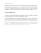
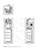
Figure A-1 ADVANCED DESIGN BOILER COMPONENT LOCATIONS 6
SECTION B: BOILER INSTALLATION INSTALLATION CODES Installations must follow these codes: · Local, state, provincial, and national codes, laws, regulations and ordinances. · National Fuel Gas Code (NFGC), ANSI Z223.1- latest edition. · National Electrical Code (NEC), ANSI/NFPA 70 - latest edition. · Standard for Controls and Safety Devices for Automatically Fired Boilers, ANSI/ASME CSD-1, when required. · For Canada only: CAN/CGA B149.1 and .2 Installation Code and C.S.A. C22. 1 C.E.C. Part 1.
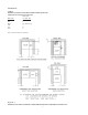
CLEARANCES TABLE 1 MINIMUM CLEARANCES FROM COMBUSTIBLE SURFACES (INDOOR ALCOVE INSTALLATIONS) Boiler Size Boiler Side 751, 1001, 1501 Floor See Note 1. Rear 1” Right 12” (Water side) Left 1” Top 0” Vent 1” Note 1. Do not install on carpeting.
Raypak Advanced Design Boilers are design certified by AGA/CGA for outdoor installation. Roof water drainage must be diverted away from boilers installed under overhangs. TABLE 2 OUTDOOR INSTALLATION MINIMUM CLEARANCES Boiler Size Boiler Side 751, 1001, 1501 Rear 6" Right 36” (Water side) Left 36" Top 0" Vent 1" WARNING: Combustion air inlet (blower air inlet) should have 6" minimum clearance from any obstruction, i.e. walls or other appliances.
SECTION C: COMBUSTION AND VENTILATION AIR COMBUSTION AND VENTILATION AIR (Indoor Units) The boiler must be supplied with sufficient quantities of non-contaminated air to support proper combustion and equipment ventilation. Combustion air can be supplied via conventional venting, where combustion air is drawn from the area immediately surrounding the boiler, or via direct vent, where combustion air is drawn directly from outside. All installations must comply with the requirements of NFGC for U.S.
All Air from Outdoors. If all combustion air is drawn from the air outside the building (the mechanical equipment room directly communicates with the outdoors), either of the following two methods can be used: Method 1: 1. The mechanical equipment room must be provided with two permanent openings, one commencing within (twelve) 12 inches of the top, and one commencing within twelve (12) inches of the bottom of the room. 2. The openings must communicate directly, or by ducts, with the outdoors. 3.
SECTION D: WATER PIPING - GENERAL The boiler should be located so that any water leaks will not cause damage to the adjacent area or structures. All units should be plumbed in accordance with the appropriate diagram from Section E, F or G or per a suitable engineered piping arrangement. CAUTION: This boiler requires forced water circulation when the burner is operating. See Table D-1 for minimum and maximum flow rates and water pump selection.
SECTION E: HYDRONIC HEATING PIPING PUMP SELECTION In order to insure proper performance of your boiler system, you must install a properly sized pump. Raypak recommends using a 20°F Delta T as design Delta T. (Delta T is the temperature difference between the inlet and outlet water when the boiler is firing at full rate).
PRESSURE DROP IN FEET OF HEAD FEEDWATER REGULATOR Raypak recommends that a feedwater regulator be installed and set at 12 PSIG minimum pressure at the highest point of system. Install a check valve or back flow device upstream of the regulator, with a manual shut off valve as required by local codes. PIPING - HEATING BOILERS All high points should be vented. Purge valves and a bypass valve should be installed. A boiler installed above radiation level must be provided with a low water cutoff device.
Figure E-2b SINGLE BOILER - PRIMARY/SECONDARY PIPING WITH CHX Figure E-3a DUAL-BOILER PIPING 15
Figure E-3b DUAL BOILER - PIPING WITH CHX Figure E-4a SINGLE BOILER - LOW TEMPERATURE APPLICATION (HEAT PUMP) PRIMARY/SECONDARY PIPING 16
SECTION F: DOMESTIC HOT WATER PIPING When designing the water piping system for domestic water applications, water hardness should be considered. Table D1 indicates the suggested flow rates for soft, medium and hard water. Hardness is specified as grains per gallon.
Figure F-1bb SINGLE BOILER DOMESTIC HOT WATER WITH ONE STORAGE TANK AND CHX (2 pump system) Figure F-1c SINGLE BOILER DOMESTIC HOT WATER WITH ONE STORAGE TANK, ONE PRE-HEAT TANK AND CHX 18
SECTION G: POOL HEATING CAUTION: Power to the heater should be interlocked with the main system pump to make sure the heater does not fire without the main system pump in operation. Improper flow control can damage the heater. Uncontrolled flow (too high) or restricted flow (too low) can seriously affect heater operation. Follow these instructions to make sure your heater is properly installed.
POOL AND SPA WATER CHEMISTRY NOTE: Chemical imbalance can cause severe damage to your heater and associated equipment. Maintain your water pH between 7.4 and 7.8 and total alkalinity between 100 and 150 p.p.m. If the mineral content and dissolved solids in the water become too high, scale forms inside the heat exchanger tubes, reducing heater efficiency and also damaging the heater (max TDS at 3000 p.p.m.). If the pH drops below 7.2, the heater will be severely damaged.
Figure G-3a DOUBLE BOILER - POOL APPLICATION 21
SECTION H: GAS SUPPLY CONNECTIONS DANGER: Make sure the gas on which the boiler will operate is the same type as specified on the boiler model and rating plate. Gas piping must have a sediment trap ahead of the boiler gas controls, and a manual shut-off valve located outside the heater jacket. A pounds to inches regulator must be installed to reduce to gas supply pressure to under 14" W.C. The regulator should be placed a minimum distance of 10 times the pipe diameter upstream of the boiler gas controls.
GAS PRESSURE REGULATOR The gas pressure regulator is nominally preset to the outlet values shown in table O-2 and O-3, within +. 1" W.C. If an adjustment is needed, turn the adjustment screw clockwise to increase pressure or counterclockwise to lower pressure.
SECTION I: ELECTRICAL POWER CONNECTIONS Installations must follow these codes: · · · · National Electrical Code and any other national, state, provincial or local codes or regulations having jurisdiction. Safety wiring must be N.E.C. Class 1. Boiler must be electrically grounded as required by N.E.C. ANSI/NFPA 70-latest edition. In Canada, C.S.A. C22. 1 C.E.C. Part 1. The boiler is wired for 120 Volts. The voltage is indicated on the tie-in leads.
MAKING THE ELECTRICAL CONNECTIONS Refer to Fig. I-2 Wiring Connection, and Fig. L-2 Wiring Diagram. 1. 2. 3. 4. 5. 6. 7. Verify circuit breaker is properly sized by referring to boiler rating plate. A dedicated motor duty circuit breaker should be provided. Turn off all power to the boiler. Verify that power has been turned off by testing with a volt-ohm meter prior to working with any electrical connections or components. Observe proper wire colors while making electrical connections.
ELECTRICAL CONNECTIONS - DOMESTIC HOT WATER CAUTION: Label all wires prior to disconnection when servicing controls. Wiring errors can cause improper and dangerous operation. Verify proper operation after servicing. DANGER - SHOCK HAZARD Make sure electrical power to the heater is disconnected to avoid potential serious injury or damage to components. The boiler is normally wired for 120 volts. The voltage is indicated on the tie-in leads.
SECTION J: VENTING CONNECTIONS GENERAL CAUTION: Proper installation of flue exhaust venting is critical for the safe and efficient operation of the boiler. For vent systems not shown in this section please contact your local authorized representative. CAUTION: Stable vent pressure is critical to the safe and proper operation of the heater. A combination of barometric dampers, balancing dampers, extractors, or draft inducers may be required to stabilize the vent pressure.
V E N T I N G 28 A R R A N G E M E N T S NOTE: PVC or CPVC vent maybe used inconjunction with CHX, special piping arrangement has to be made. Contact manufacturer for details.
Support of Vent Stack The weight of the vent stack or chimney must not rest on the boiler vent connection. Support must be provided in compliance with applicable codes. The vent should also be supported to maintain proper clearances from combustible materials. Use insulated vent pipe spacers where the vent passes through combustible roofs and walls. Vent Terminal Location NOTICE: During winter months check the vent cap and make sure no blockage occurs from build up of snow.
Venting Installation Tips Support piping: · horizontal runs- at least every five (5) feet. · vertical runs - use braces: · under or near elbows Follow items listed below to avoid personal injury or property damage. · · · · Cut nonmetallic vent pipe with fine-toothed hacksaw (34 teeth per inch). Do not use nonmetallic vent pipe or fittings that are cracked or damaged. Do not use nonmetallic vent fittings if they are cut or altered.
SECTION J-1 Natural Draft Vertical Venting Without Add-on Condensing Heat Exchanger (Category I) Figure J-1 NATURAL DRAFT VERTICAL VENT WITHOUT ADD-ON CONDENSING HEAT EXCHANGER* NOTE: *Rear venting is recommended to minimize interference with water piping **Vent lengths are based on a lateral length of 2 feet. Refer to the latest edition of the National Fuel Gas Code for further details. (ANSI Z223.1), or in Canada the latest edition of CAN/CGA-B149.1 and B149.2.
• Natural Draft Vertical Venting System Installation Natural draft venting uses the natural buoyancy of the heated flue products to create a thermal driving head that expels the exhaust gases from the flue. The negative draft must be within the range of 0.01 to 0.08” negative W.C. to insure proper operation. The vent material must be in accordance with the above instructions for vent materials. Vent material must be listed by a nationally recognized test agency.
Common venting systems may be too large when an existing unit is removed. At the time of removal of an existing appliance, the following steps must be followed with each appliance remaining connected to the common venting system placed in operation, while the other appliances remaining connected to the common venting system are not in operation. a) Seal any unused opening in the common venting system.
SECTION J-2 Horizontal Thru-Wall Venting Without Add-on Condensing Heat Exchanger (Category III) Figure J-2 HORIZONTAL THRU-WALL VENTING WITHOUT ADD-ON CONDENSING HEAT EXCHANGER (CATEGORY III) • Horizontal Thru-wall Direct Venting System (Category III) Installation These installations utilize the boiler-mounted blower to vent the combustion products to the outdoors. Combustion air is taken from inside the room and the vent is installed horizontally through the wall to the outdoors.
The total length of the thru-wall exhaust vent system cannot exceed sixty-five (65) feet in length for the flue outlet. Each elbow used is equal to ten (10) feet of straight pipe. This will allow installation in one of the four following combinations. · · · · 65’ of straight flue pipe. 55' of straight flue pipe and one elbow. 45' of straight flue pipe and two elbows. 35' of straight pipe and three elbows. The direct vent cap is not considered in the overall length of the venting system.
SECTION J-3 Horizontal Thru-Wall Direct Venting/Combustion Air (Category III) Figure J-3 HORIZONTAL THRU-WALL DIRECT VENTING WITHOUT ADD-ON SECONDARY CONDENSING HEAT EXCHANGER 36
• Horizontal Thru-wall Direct Venting System (Category III) Installation These installations utilize the boiler mounted blower to draw combustion air from outdoors and vent combustion products to the outdoors. The total length of the thru-wall exhaust vent cannot exceed forty-five (45) feet in length for the flue outlet. Each elbow used is equal to ten (10) feet of straight pipe. This will allow installation in one of the three following combinations. · · · 45’ of straight flue pipe.
SECTION J-4 Vertical Direct Venting/Combustion Air (Category I) Figure J-4 VERTICAL DIRECT VENTING WITHOUT ADD-ON CONDENSING HEAT EXCHANGER *Vent lengths are based on a lateral length of 2 feet. Refer to the latest edition of National Fuel Gas Code for further details (ANSI Z223.1) or in Canada the latest edition of CAN/CGA-B149.1 and B149.2.
• Vertical Direct Venting System Installation These installations utilize the boiler mounted blower to draw combustion air from outdoors and uses the natural buoyancy of the heated flue products to create a thermal driving head that expels the exhaust gases from the flue. The negative draft must be within the range of 0.01 to 0.08” negative W.C. to insure proper operation. The vent material must be in accordance with the above instructions for vent materials.
SECTION J-5 Vertical Venting With Add-On Condensing Heat Exchanger (Category IV) Domestic Water Figure J-5 VERTICAL VENT (CATEGORY IV) WITH ADD-ON CONDENSING HEAT EXCHANGER 40
• Vertical Vent (Category IV) with Add-on Condensing Heat Exchanger Installation These installations utilize the boiler mounted blower to vent the combustion products to the outdoors. Combustion air is taken from inside the room and the vent is installed vertically through the roof to the outdoors. Adequate combustion and ventilation air must be supplied to the boiler room in accordance with the National Fuel Gas Code or, in Canada, the latest edition of CAN/CGA-B149.1 AND .2.
SECTION J-6 Horizontal Thru-wall Venting With Add-on Condensing Heat Exchanger (CHX) Figure J-6 HORIZONTAL THRU-WALL VENTING WITH ADD-ON CONDENSING HEAT EXCHANGER 42
• Horizontal Thru-wall Venting System (Category IV) Installation This installation utilize the boiler mounted blower to vent the combustion products to the outdoors. Combustion air is taken from inside the room and the vent is installed horizontally through the wall to the outdoors. Adequate combustion and ventilation air must be supplied to the boiler room in accordance with the National Fuel Gas Code or, in Canada, the latest edition of CAN/CGA-B149.1 and .
SECTION J-7 Horizontal Thru-Wall Direct Venting/Combustion Air With Add-On Condensing Heat Exchanger (Category IV) Figure J-7 HORIZONTAL THRU-WALL DIRECT VENTING WITH ADD-ON CONDENSING HEAT EXCHANGER 44
• Horizontal Thru-wall Direct Venting System With Add-on Condensing Heat Exchanger (Category IV) Installation These installations utilize the boiler mounted blower to draw combustion air from outdoors and vent combustion products to the outdoors. UL 17-38 Certified Venting Material (e.g. AL29-4C) MUST be used. The vent must be installed to prevent the flue gas leakage. Care must be taken during assembly to insure that all joints are sealed properly and are airtight. For certain installations, i.e.
SECTION J-8 Vertical Direct Venting/Combustion Air With Add-on Condensing Heat Exchanger (Category IV) Figure J-8 VERTICAL DIRECT VENTING WITH ADD-ON SECONDARY CONDENSING HEAT EXCHANGER 46
• Vertical Direct Venting System With Add-on Condensing Heat Exchanger (Category IV) Installation These installations utilize the boiler mounted blower to draw combustion air from outdoors and vent combustion products to the outdoors. UL 17-38 Certified Venting Material (e.g. AL29-4C) MUST be used. The vent must be installed to prevent flue gas leakage. Care must be taken during assembly to insure that all joints are sealed properly and are airtight. For certain installations, i.e.
Outdoor Installation with Add-On Condensing Heat Exchanger Outdoor models are self -venting when installed with the factory-supplied non-restricted direct vent cap and require no additional vent piping. This special vent cap is provided with the boiler in accordance with AGA/CGA requirements. It must be installed directly on the boiler in a horizontal position. Notching of the vent cap mounting flange may be necessary to clear outlet piping on some models. See Section B for correct clearances.
SECTION K CONDENSATE DRAIN WARNING: All condensation should be disposed of according to local, county, state, and federal laws. Refer to NFGC, section 7.9, for additional information. The Condensing Heat Exchanger (CHX) can generate up to 1 (one) gallon per hour (GPH) of condensate for every 100,000 BTUH. The maximum condensation rate for the ADB 751 is 7.5 GPH, the ADB 1001 is 10 GPH, and the ADB1501 is 15 GPH.
SECTION L CONTROLS WARNING: Installation, adjustment and service of boiler controls including timing of various operating functions must be performed by a qualified installer or service agency. Failure to do so may result in control damage, boiler malfunction, property damage, personal injury, or death. WARNING: Turn off the power to the boiler before installation, adjustment or service of the Central Point Wiring board or any boiler controls.
In addition to monitoring and displaying boiler status, the CPW board controls the timing of various operating functions including: boiler pump turn-off delay, blower fan pre-purge, and blower fan post-purge. The location of each useradjustable timing is shown in Figure L-1. Figure L-1 CPW Board • Pump Turn-off Delay The CPW board has a built-in pump driver with pump turn-off delay, which allows the operator to set how long the pump will run after the boiler shuts off.
• Freeze Protection Feature The CPW board is programmed to turn-off the blower in case there is a lock-out condition. If there is a call for heat signal, and the pilot valve signal is removed and not reactivated within a pre-set time for any reason, the CPW board will turn off the blower to prevent blowing cold air continuously and freezing the heat exchanger. The blower drives will open and the system will lock in the off state.
Figure L-2 WIRING DIAGRAM 53
IGNITION CONTROL MODULE The intermittent ignition device conserves energy by automatically extinguishing the pilot when the desired temperature is reached. When additional heat is needed, the combustion air blower starts to purge all air from the combustion chamber for about 45 seconds. On proof of air flow, the air proving switch closes and the pilot reignites electrically, eliminating the fuel costs of maintaining a constant pilot.
LOW WATER CUT OFF (OPTIONAL) The low water cut off automatically shuts down the burner whenever water level drops below the level of the sensing probe. A 3 second time delay prevents premature lockout due to temporary conditions such as power fluctuations or air pockets. LOW WATER CUT OFF HIGH AND LOW GAS PRESSURE SWITCHES - MANUAL RESET The low gas pressure switch mounts upstream of the gas pressure regulator to ensure that sufficient gas pressure is present for proper regulator performance.
SECTION M: GENERAL SAFETY PRECAUTIONS To meet commercial water use needs, an external operating control for this hot water boiler is adjustable up to 210°F. However, water temperatures over 125°F can cause instant severe burns or death from scalds. The preferred starting point for setting the control for supplying general purpose hot water is 125°F. Safety and energy conservation are factors to be considered when setting the water temperature on the thermostat.
SECTION N: PRE-START-UP FILL THE SYSTEM: 1. 2. 3. 4. 5. 6. 7. Close manual and automatic air vents and drain cock. Fill to correct system pressure. Correct pressure will vary with each application. Open automatic air vent two turns. Slowly feed water to boiler. Starting on the lowest floor, open air vents one at a time until water squirts out. Close vent. Repeat with remaining vents. Close manual water feed valve when correct boiler pressure is reached. INSPECT VENTING SYSTEM: 1. 2.
Blower "T" fitting detail.
SECTION O: ADB INITIAL START-UP CAUTION: Verify that the vent system and combustion air supply have been approved. 1.0 TOOLS NEEDED • • • • • • • • • • One 8-0-8 , 16” scale manometer (or larger) Four 4-0-4, 8” scale manometers (or larger) “T” fitting 7/16” and 1/2" open end wrenches Small and large flat-head screwdrivers Volt meter Amp probe Elec. Dual reading thermometer with strap on sensors 3/16” Allen wrench Combustion analyzer 2.
2.4 Check the Gas Supply Pressure, Location (1) • • • • • Leave pilot gas valve and first manual gas valve closed; Slowly turn on main gas shut-off valve (outside the unit); Read the gas supply pressure from the manometer (Location 1); If pressure is > 14" W.C., Turn off the valve; Check if the service regulator is installed and/or adjust the service regulator. 3.0 START-UP NOTICE: Reference the start-up pressures settings located on the side of the control box. 3.1 Blower Adjustment 1. 2. 3. 4.
TABLE O-3: Pressure Settings and Emission Guidelines (True Readings) for LP GAS Note: For different gas control options, call the factory for proper pressure settings (i.e. IRI, etc) NOTICE: Emissions will vary with different applications (hydronic, water heater, or pool), venting (including direct vent), ambient conditions (T, P, and humidity), and the condition of the boiler. NOTICE: For high altitude (above 5000 ft), call the factory for proper pressure settings. 3.3 Main Burner Adjustment 1. 2. 3.
3.5 Follow-up • • • • • • • • • Safety checks must be recorded as performed; Turn unit on; After main burner ignition.
SECTION Q: OPERATION OPERATING INSTRUCTIONS Lighting Instructions 1. 2. 3. 4. STOP! Read the safety information first. Set the thermostat to the lowest setting. Turn off all electric power to the appliance. This appliance is equipped with an ignition device which automatically lights the burner. Do Not try to light the burner by hand. 5. Remove upper front panel. 6. Turn on main manual gas valve and pilot manual gas valve. 7. Wait five (5) minutes to clear out any gas.
SECTION R: MAINTENANCE SUGGESTED MINIMUM MAINTENANCE SCHEDULE: Regular service by a qualified service agency and maintenance must be performed to assure maximum boiler operating efficiency. Maintenance as outlined below may be performed by the owner. Yearly (Beginning of each heating season): 1. 2. 3. 4. 5. 6. 7. 8. 9. 10. 11. 12. 13. Annual service call by qualified service agency. Visually check top of vent for soot. Call service person to clean. Some sediment at bottom of vent is normal.
CLEANING BOILER HEATING SURFACES: The following service procedures must be performed ONLY by a qualified service agency. Boiler owner should not attempt these procedures. 1. 2. If you find soot in top of vent elbow (some sediment in bottom of vent is normal) - remove vent attachment to the ADB and clean flue exhaust baffle inside the boiler. Also check burner, replace if damaged. If you find rust deposits in vent elbow - check for high water flowrate or low inlet water temperatures. Clean boiler as above.
SECTION S: CONNECTING CONDENSING HEAT EXCHANGER (CHX) Refer to Figure S-1 for the following steps: NOTICE: 1. 2. 3. 4. 5. 6. 7. 8. 9. 10. 11. 12. 13. Connect the vent before connecting the water piping. Install unions on water inlet and outlet of CHX for ease of maintenance. The CHX require cleaning as often as once the year. Remove the shroud. Remove the top cover. Secure the 15° elbows (supplied) as shown one on each side of the CHX, using the stainless steel screws (supplied).
APPENDIX A INSIDE COMBUSTION AIR CONTAMINATION: All boilers experience some condensation during start-up. The condensate from flue gas is slightly acidic. In most cases the pH level is not harmful to vents or drains. When combustion air is contaminated by vapors from products in areas listed below, the acidic levels in the condensate increase. Higher acidic levels attack many materials, including stainless steel commonly used in high efficiency systems.
START-UP SETTINGS TODAY'S DATE: __________________________________________________ PRESSURE SETTINGS: Blower (burner off)……………… ______ "W.C. Pilot……………………………… ______ "W.C. Main Burner (Top)……………. ______ "W.C. Main Burner (Bottom)………… ______ "W.C. Blower (burner on) ……………… ______ "W.C. Supply Gas (static) ……………… ______ "W.C. Supply Gas (dynamic) …………… ______ "W.C. Power Supply……............……….
LIMITED PARTS WARRANTY ADVANCED DESIGN BOILER™ SCOPE: Raypak, Inc. ("Raypak") warrants to the original owner that all parts of this boiler which are actually manufactured by Raypak will be free from failure under normal use and service for the specified warranty periods and subject to the conditions set forth in this Warranty. Labor charges and other costs for parts removal or reinstallation, shipping and transportation are not covered by this Warranty but are the owner's responsibility.
www.raypak.com Raypak, Inc., 2151 Eastman Avenue, Oxnard, CA 93030 (805) 278-5300 FAX: (800) 872-9725 Raypak Canada LTD, 2805 Slough Street, Mississauga, Ontario, Canada L4T 1G2 (905) 677-7999 FAX: (905) 677-8036 Raypak Australia Pty. Ltd, 7 Geddes Street, Mulgrave, Victoria, Australia 3170 (613) 9560 4944 FAX: (613) 9560-4974 8/98 Litho in U. S. A.