INSTALLATION AND OPERATING INSTRUCTIONS CATALOG NO. 3000.50D Effective: 01-01-03 Replaces: 03- 01-97 Models 090A, 135A, 195A Type WH ECONOPAK WATER HEATERS FOR YOUR SAFETY Do not store or use gasoline or other flammable vapors and liquids or other combustible materials in the vicinity of this or any other appliance. To do so may result in an explosion or fire. WARNING: Improper installation, adjustment, alteration, service or maintenance can cause property damage, personal injury or loss of life.
Contents 3 1. RECEIVING EQUIPMENT 3 4 2. GENERAL SPECIFICATIONS AND DIMENSIONS General Safety Precautions 6 6 6 6 6 7 8 9 10 11 12 3. INSTALLATION PROCEDURES - Code Requirements - Mounting Base - Clearance Requirements - Combustion/Ventilation Air - Venting Connections - Common Vents - Gas Supply Connections - Water Connections & System Piping - Electrical Wiring - Wiring Diagrams 13 13 13 14 17 18 4.
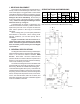
1. RECEIVING EQUIPMENT On receipt of your equipment it is suggested that you visually check for external damage to the carton. If the carton is damaged, it is suggested that a note be made on the Bill of Lading when signing for equipment. Remove the heater from the carton and if it is damaged report the damage to the carrier immediately. Be sure that you receive the number of packages indicated on the Bill of Lading. Claims for shortages and damages must be filed with carrier by consignee.
General Safety Precautions Be sure to read and understand the entire Instruction Manual before attempting to install or operate this water heater. Pay particular attention to the following general Safety Precautions. Failure to follow these warnings could result in a fire or explosion, causing property damage, bodily injury or death. Should you have any problems understanding the instructions in this manual, STOP, and get help from a qualified installer or service technician or the gas supplier.
General Safety Precautions The following chart details the relationship of water temperature and time with regard to scald injury and may be used as a guide in determining the safest water temperature for your applications. To meet commercial hot water requirements, the tankstat is adjustable up to 190°F. However, water temperatures over 125°F. can cause severe burns instantly or death from scalds. This is the preferred starting point for setting the control for supplying general purpose hot water.
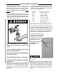
3. INSTALLATION PROCEDURES operation and service (circulator replacement, control replacement, etc.) CODE REQUIREMENTS Installation must be in accordance with local codes, or, in the absence of local codes, with the latest editions of the National Fuel Gas Code, ANSI Z223.1,/ NFPA 54, and the National Electrical Code, ANSI/ NFPA 70. In Canada installations must conform with the current CAN/CGA B149.1 or .2 and the Canadian Electrical Code Part 1 CSA C22.2 No.1.
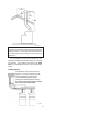
2) If the heater room is located against an outside wall and air openings can communicate directly with the outdoors, the two openings on the outside wall must each have a net free area, in square inches as follows: The discharge opening must be a minimum of two feet vertically from the roof surface and at least two (2) feet higher than any part of the building within ten (10) feet. Vent stack shall be at least five (5) feet in vertical height above the drafthood outlet.
Fig.# 8191.1 WARNING: These heaters must not be connected into any portion of mechanical draft systems operating under positive pressure. To do so may cause the flue products to be discharged into the living space causing serious health injury. For connections to gas vents or chimneys, vent installations shall be in accordance with Part 7, Venting of Equipment, of the National Fuel Gas Code, ANSI Z223.1, or applicable provisions of the local building codes.
At the time of removal of an existing heater, the following steps shall be followed with each appliance remaining connected to the common venting system placed in operation, while the other appliances remaining connected to the common venting system are not in operation. GAS SUPPLY CONNECTIONS The inlet gas connection of the heater gas valve is 1/2". Provide an adequate gas piping supply line no smaller than 1/2", according to the chart below: (a) Seal any unused openings in the common venting system.
The gas valve is provided with pressure taps to measure gas pressure upstream of the gas valve and downstream which is the same as the manifold pressure. WATER CONNECTIONS & SYSTEM PIPING The pipe size and fittings between the heater and the tank should be at least 1" for model 90, and 1-1/4" for models 135 and 195.
ELECTRICAL WIRING The electrical power supply requirement for these heaters is 115 volts, 60 Hz. Field wiring connections and electrical grounding must comply with the local codes, or in the absence of local codes, with the latest edition of the National Electrical Code, ANSI/NFPA 70. Provide a separate fused circuit from the main electrical panel to the heater, and a disconnecting means within sight of the heater.
WIRING DIAGRAM: STANDING PILOT MODELS 90, 135 and 195 WARNING: SHOCK HAZARD LINE VOLTAGE IS PRESENT. BEFORE SERVICING TANKSTAT OR HEATER, TURN OFF ELECTRICAL POWER TO THE HEATER AT THE MAIN DISCONNECT OR CIRCUIT BREAKER. FAILURE TO DO SO COULD RESULT IN SEVERE PERSONAL INJURY OR DEATH. WIRING DIAGRAM: INTERMITTENT IGNITION DEVICE (IID) MODELS 90, 135 and 195 *Field Installed WARNING: SHOCK HAZARD LINE VOLTAGE IS PRESENT.
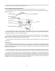
4. SERVICING PROCEDURES Circulator GENERAL LOCATION OF CONTROLS CONTROL BOX COMPONENT LOCATIONS Manual Reset Limit Pressure Relief Valve Field Wiring Compartment Ignition Module (Auto Ignition Only) Temperature Sensor Ignition Module (Auto Ignition Only) Transformer Roll-Out Sensor SEQUENCE OF OPERATION INTERMITTENT IGNITION DEVICE (IID) Heaters equipped with the IID system will automatically light the pilot burner first and then the main burner, each time there is a call for heat from the tankstat.
START-UP PROCEDURES SECTION 1. Filling the System Fill system with water. Purge all air from the system using purge valve sequence. After system is purged of air, lower system pressure. Flush system before putting into operation to assure that foreign material does not damage pump seals. SECTION 2. Checking the Circulator Before lighting the heater and after system is filled, make sure that circulator is operating properly. Manual gas valve should be off.
8. Push down and hold the red reset button in, immediately light the pilot with a match. Continue to hold down red reset button for about one minute after the pilot is lighted. Release red reset button and it will pop back up. Pilot should Remain lighted. If it goes out, repeat steps 4 through 8. * If red reset button does not pop up when released stop and immediately call your service technician or gas supplier.
FOR INTERMITTENT IGNITION (IID) WITH HONEYWELL OR ROBERTSHAW GAS VALVE 1. 2. 3. 4. STOP! Read the safety information above. Set the tankstat to the lowest setting. Turn off all electric power to the appliance. This heater is equipped with an ignition device which automatically lights the pilot. Do not try to light the pilot by hand. GAS CONTROL KNOB SHOWN IN "ON" POSITION TO TURN OFF GAS TO HEATER 1. Set the tankstat at the lowest setting. 2.
INSPECTION PROCEDURES BURNERS Fig.# 8935.0 Clean main burners and air louvers of dust, lint and debris. Keep heater area clear and free from combustibles and flammable liquids. Do not obstruct the flow of combustion and ventilating air. Make visual check of burner and pilot flame. Yellow flame indicates clogging of air openings. Lifting or blowing flame indicates high gas pressure. Low flame indicates low gas pressure. Pilot Adjustment 4" Max. ROBERTSHAW 7200 GAS VALVE (Models 135 & 180) e.
BURNER DRAWER REMOVAL PROCEDURE FOR CLEANING FLUE GAS PASSAGE-WAYS 1. Shut off power and gas supply to the heater. Disconnect union(s) and pilot tubing when present; then loosen and remove burner hold down screws. 2. Disconnect wires at gas valve and slide burner drawer out. Soot will clog areas behind fins and cause eventual tube failure. Any sign of soot at base of burners or around outer jacket indicates a need for cleaning. 1. Lift off draft hood and flue collector by removing bolts and screws. 2.
HEAT EXCHANGER RE-ASSEMBLY 1. Heat exchanger water header O-rings should be replaced with new ones. 2. Install inlet-outlet and return water headers and install header retainer nuts and torque nuts evenly. 3. Replace "V" baffles. 4. Install thermostat sensing bulbs in header wells and replace bulb retaining clips. 5. Install inlet and return pipes in water headers using pipe thread sealant. 6. Install water pressure relief valve, sensor probe, and low water cutoff devices if so equipped. 7.
5. TROUBLE SHOOTING GUIDE IMPORTANT NOTICE These instructions are primarily intended for the use of qualified personnel specifically trained and experienced in the installation of this type of heating equipment and related system components. Installation and service personnel may be required by some states to be licensed. Persons not qualified shall not attempt to install this equipment nor attempt repairs according to these instructions. PROBLEM(S) 1)When tankstat is turned on, heater does not operate.
3) Pilot Outage. (Standing pilot models) 4) Yellow lazy flame. 1) Too low or too high gas pressures. 2) Restricted pilot. 3) Weak thermocouple. 1) Adjust inlet gas pressure as shown on rating plate. 2) Clean pilot orifice. 3) Replace thermocouple. 1) Too low gas pressure. 1) Adjust manifold pressure as shown 2) Restricted burner intake ports. 3) Restricted gas line. 5) Sooting 1) Insufficient combustion air. 2) Improper venting. 3) Severe yellow burner flames. 21 on rating plate.
ADJUSTMENTS/REPLACEMENTS OF COMPONENTS 3. Flame Roll-out Switch Replacement a) Shut off electrical power to the heater. b) Remove wiring connections to switch. c) Remove screws (2) holding the switch. d) Reverse above procedure to re-install. CAUTION: Label all wires prior to disconnection when servicing controls. Wiring errors can cause improper and dangerous operation. Verify proper operation after servicing. 4. Vent Thermal Switch Replacement a) Shut off electrical power to the heater.
6. REPLACEMENT PARTS LIST NOTE: To supply the correct part it is important that you state the model number, serial number and type of gas when applicable. Any part returned for replacement under standard company warranties must be properly tagged with RAYPAK return parts tag, completely filled in with the heater serial number, model number etc., and shipped to the Company freight prepaid.
5-S HONEYWELL IID HONEYWELL STANDING PILOT ROBERTSHAW STANDING PILOT 1-P 3-P 3-P 1-P 2-P 1-P 2-P 6-P 2-P 9-P 6-P 8-P Fig. # 8189.4 6-P 8-P 8-P Fig. # 9112 24 Fig. # 8190.
LIMITED PARTS WARRANTY ECONOPAK WATER HEATERS MODELS WH - 90 TO 195 SCOPE: Raypak, Inc. ("Raypak") warrants to the original owner that all parts of this water heater which are actually manufactured by Raypak will be free from failure under normal use and service for the specified warranty periods and subject to the conditions set forth in this Warranty.
www.raypak.com Raypak, Inc., 2151 Eastman Avenue, Oxnard, CA 93030 (805) 278-5300 FAX (800) 872-9725 Raypak Canada LTD, 2805 Slough Street, Mississauga, Ontario, Canada L4T 1G2 (905) 677-7999 FAX (905) 677-8036 Litho in U.S.A.