CATALOG NO.: 5000.59B Effective Date: 4-09-08 Replaces: 3-15-99 Installation and Operating Manual T-3 Raypak B6000 Modbus System Protocol Interface T-3 Communications Interface Raypak B6000 Boiler Controller to Modbus Interface Card 1 P/N 240729 Rev.
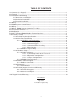
TABLE OF CONTENTS 1.0 Contents (as shipped) ----------------------------------------------------------------------------------- 3 2.0 Forward ----------------------------------------------------------------------------------------------------- 3 3.0 Installation and Mounting -------------------------------------------------------------------------------- 4 3.1 Dimensions and Weight------------------------------------------------------------------------- 4 3.
T-3 (Raypak B6000 System Protocol Interface) Contents Quantity COMPACT DISC (CD) T-3 EPROM (CPX.XNMn) in small black ESD box 1 1 1 Check packaging for damage or missing components. IMPORTANT NOTICE: These instructions are intended for the use by qualified personnel only, specifically trained and experienced in the installation of this type of equipment and related system components. Installation and service personnel may be required by some states to be licensed.
T-3 INSTALLATION AND MOUNTING The T-3 Module should be mounted on a permanent base not subject to vibrations, moisture or dust. It should be readily accessible, for serviceability. DIMENSIONS AND WEIGHT 15 3/4” H 8” W 5 3/4” D 14 LBS MECHANICAL INSTALLATION Mount the System Protocol Interface within five (5) feet of B6000 System Control Box. The Gateway enclosure must be mounted vertically with conduit holes facing downward. Conduit holes are provided to accommodate standard conduit fittings.
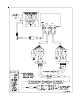
WIRING T-3 1. Turn off power to the B6000 System Control Box. 2. Open front door of System Protocol Interface Gateway Enclosure. 3. Remove four screws and the lower cover, revealing the field wiring blocks. 4. Attach wires from interface card to the field wiring side of left terminal block (N+, N-, GND, NC). Refer to diagram in this user manual. 5. Open front door of the B6000 System Control Box. 6. Remove four screws and the lower cover, revealing the field wiring blocks in lower left. 7.
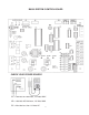
B6000 SYSTEM CONTROL BOARD CHECK YOUR POWER SOURCE AC = 108 Volts AC Minimum, 132 Volts MAX AB = 108 Volts AC Minimum, 132 Volts MAX BC = Must be less than 1.
11.0. T-3 Revision 1.0 Raypak B6000 Modbus™ Protocol Interface Please Read this Notice Successful application of the T-3 card requires a reasonable working knowledge of the Raypak B6000 Boiler Control, and the application in which the combination is to be used. For this reason, it is important that those responsible for implementing the T-3 satisfy themselves that the T-3 and B6000 Boiler Control combination will meet the needs of the application. This manual is provided to assist the user.
11.1. Product Specifications The T-3 card is a hardware product designed to be the communications front end for the Raypak B6000 Boiler Control and a modbus Master Host.
11.2.0 11.2.1 Slave Port Functionality Modbus Communications The T-3 Modbus Slave card runs the RTU version of the Modbus protocol. This capability allows the module to communicate data from a Raypak B6000 Boiler Control to a Modbus Master host, and vice-versa. The module supports both point-to-point implementation as well as multi-drop implementations. The following discusses the functional capabilities of the T-3 card. 11.2.1.
.2.1.4 Data Integrity As in all good protocols, there must exist a level of data integrity checking to verify, with some degree of assurance, the quality of the transmitted data. The Modbus protocol supports two types of error checking: • • RTU Mode: 16 bit cyclic redundancy check (CRC-16) One bit parity check CRC-16: When the master generates a message, a 16 bit CRC value is added to the end of the transmitted packet. The CRC value is generated using a series of the bit shifts and manipulations.
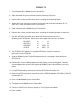
Hardware Setup 11.3.0 11.3.1.1 1500 Interface Card Setup 11.3.1.1 Connecting Power to the T-3 Card The T-3 Card requires an external source of DC voltage. The DC source voltage should be between 9V and 30V. The power is connected to TB1, located near the two 9 pin serial port connections. The connection to TB1 is as follows: TB1-1 9-30 VDC (+) TB1-2 Common (-) 11.3.1.2 Dip Switch Configuration The T-3 card is configured primarily through two sets of dip switches.
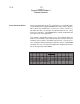
Example Addresses = 0 to 33 8 7 6 5 4 3 0 0 0 0 0 0 0 0 0 0 0 0 0 0 0 0 0 0 0 0 0 0 0 0 0 0 0 0 0 1 0 0 0 0 0 1 0 0 0 0 0 1 0 0 0 0 0 1 0 0 0 0 1 0 0 0 0 0 1 0 0 0 0 0 1 0 0 0 0 0 0 0 0 0 0 0 1 1 0 0 0 0 1 1 0 0 0 0 1 1 0 0 0 0 1 1 0 0 0 1 0 0 0 0 0 1 0 0 0 0 0 1 0 0 0 0 0 1 0 0 0 0 0 1 0 1 0 0 0 1 0 1 0 0 0 1 0 1 0 0 0 1 0 1 0 0 0 1 1 0 0 0 0 1 1 0 0 0 0 1 1 0 0 0 0 1 1 0 0 0 0 1 1 1 0 0 0 1 1 1 0 0 0 1 1 1 0 0 0 1 1 1 0 0 1 0 0 0 0 0 1 0 0 0 2 0 0 1 1 0 0 1 1 0 0 1 1 0 0 1 1 0 0 1 1 0 0 1 1 0 0 1 1 0 0 1
The parameters are defined as follows: Modbus Slave Address: Each of the separate drop offs of a Modbus host must have a different slave address. The slave address is selected by encoding the slave address in a binary form using the dip switches. 11.3.1.3 T-3 Jumper Configurations The T-3 card has five sets of jumpers on the board. Generally, the default jumper positions will be adequate for most applications, with JP4 and JP5 being the only jumpers that should ever need to be reviewed.
11.4.0 Modbus Protocol Support 11.4.1 11.4.2 Modbus Commands The T-3 card supports a command subset of the Modbus Specification consisting primarily of the Function Codes required to read and write data. The following sections detail the different commands supported by the card. Function Code Address Command Slave Driver Range 2 Read Input Status 3 Read Multiple Registers 40001 to 40138 The Module returns word data from the register space.
11.5.0 Diagnostics Several hardware diagnostics capabilities have been implemented using the LED indicator lights on the front of the T-3 card. The possible conditions as indicated by the lights are: 11.5.1 LED Indicators Several hardware diagnostics capabilities have been implemented using the LED indicator lights on the front of the module.
11.6.0 ProSoft Support, Service and Warranty 11.6.1 Technical Support ProSoft Technology survives on its ability to provide meaningful support to its customers. Should any questions or problems arise, please feel free to contact us at: ProSoft Technology, Inc. 9801 Camino Media Suite 105 Bakersfield, CA 93311 (805) 664-7208 (805) 664-7233 FAX Before calling for support, please prepare yourself for the call.
LIMITED WARRANTY T-3 SCOPE OF WARRANTY: Raypak, Inc. (“Raypak”) warrants to the original owner the T-3 to be free from defects in materials and workmanship under normal use and service for the applicable warranty period. In accordance with the terms of this Limited Warranty, RAYPAK will furnish a replacement or repair, at our option, any defective part which fails in normal use and service during the applicable warranty period.
APPENDIX A Modbus Register Map A-1 19
Raypak Modbus Register Assignments Function Function Function Type R/W R/W R/W R/W R/W R/W R/W R/W R/W R/W R/W R/W R/W R/W R/W R/W R/W R/W R/W R/W R/W R/W R/W R/W R/W R/W R/W R/W R/W R/W R R R 2 10001 10017 10018 R R R R R R R R R R R R R R R R R 10209 10210 10211 10212 10213 10214 4 30001 30002 30003 30004 30005 30006 30007 30008 30009 30010 30011 30012 30013 30014 30015 30016 30017 30018 30019 30020 30021 30022 30023 30024 30025 30026 30027 30028 30029 30030 30031 30032 3,6 40001 40002 40003 40004
R R R R R 10215 10216 10217 10218 10219 R R R R R R R R R R R 10225 10226 10227 10228 10229 10230 10231 10232 10233 10234 10235 R R R R R R R R R R R 10241 10242 10243 10244 10245 10246 10247 10248 10249 10250 10251 R R R R R R R R R R R 10257 10258 10259 10260 10261 10262 10263 10264 10265 10266 10267 R R R R R R R R R R R 10273 10274 10275 10276 10277 10278 10279 10280 10281 10282 10283 6 7 8 9 10 High Limit (0 = Normal, Thermostat - Operating aquastat (not fault) (0 = Normal, Manual Override (
R R R R R R R R R R R 10289 10290 10291 10292 10293 10294 10295 10296 10297 10298 10299 R R R R R R R R R R R 10305 10306 10307 10308 10309 10310 10311 10312 10313 10314 10315 R R R R R R R R R R R 10321 10322 10323 10324 10325 10326 10327 10328 10329 10330 10331 R R R R R R R R R R R R R R R R R R 30049 40049 bit 0 1 2 3 4 5 6 7 8 9 10 Boiler #6 Status Word Boiler #6 Boiler Not On Line (0 = Normal, 1 = Alarm) Boiler Operation (0 = Firing, 1 = Ready) Low Water Cutoff (0 = Normal, 1 = Alarm) Low Pr
R R R R R R R R R R R R R 30070 30071 30072 30073 30074 30075 30076 30077 30078 30079 30080 30081 30082 40070 40071 40072 40073 40074 40075 40076 40077 40078 40079 40080 40081 40082 TS - Boiler Start TS - Boiler Start TS - Boiler Start TS - Boiler Start TS - Boiler Start TS - Boiler Start TS - Boiler Start TS - Boiler Start Time - Hrs Time - Min Time - DWK Lead Change Hrs Remaining 30083 40083 Bit 0 = Setback on (1) R R R R R R R R R R R R R R R R R R R R R R R R R R R R R R 30084 30086 30088 30090
www.raypak.com Raypak, Inc. 2151 Eastman Avenue, Oxnard, CA 93030 (805) 278-5300 • FAX (805) 278-5489 Litho in U.S.A.