
user manual

4
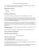
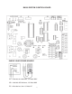
T-3 INSTALLATION AND MOUNTING
The T-3 Module should be mounted on a permanent base not subject to vibrations, moisture or
dust. It should be readily accessible, for serviceability.
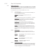
DIMENSIONS AND WEIGHT
15 3/4” H 14 LBS
8” W
5 3/4” D
MECHANICAL INSTALLATION
Mount the System Protocol Interface within five (5) feet of B6000 System Control Box.
The Gateway enclosure must be mounted vertically with conduit holes facing downward. Conduit
holes are provided to accommodate standard conduit fittings. Additional or larger conduit fit-
tings that may be required should be located on the bottom of the module. Mount the Interface
with 3/8” or 1/4” hardware in four (4) places.
A Minimum of six (6) inches clearance on all sides is required and a minimum of eighteen (18)
inches clearance from the front is required for service access. The hinged side of the box is to
the right and the clearance (minimum 3” from bolt hole on the right side) should be sufficient to
open the cover.
A sub-panel containing the disconnect switches and surge suppressors is required at or near the
equipment location(s).
For accessibility remove the lower interior panel, by removing the four (4) access screws.
INSTALL CONDUIT AS APPROPRIATE.
ELECTRICAL CHARACTERISTICS
120 VAC, 0.25A, 60 Hz
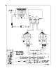
ELECTRICAL INSTALLATION
120 VAC FEEDER CIRCUITS
Install a surge protection device sized appropriately for your installation.
Install separate disconnect means for each load. Pull in appropriately sized wire for equipment
as defined by NEC and/or local code.
It is strongly recommended that the Communications Interface, B6000 System Control Module
and the B6000 Boiler Control Module be supplied from the same source power.