
user manual

5
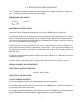
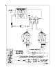
WIRING T-3
1. Turn off power to the B6000 System Control Box.
2. Open front door of System Protocol Interface Gateway Enclosure.
3. Remove four screws and the lower cover, revealing the field wiring blocks.
4. Attach wires from interface card to the field wiring side of left terminal block (N+, N-,
GND, NC). Refer to diagram in this user manual.
5. Open front door of the B6000 System Control Box.
6. Remove four screws and the lower cover, revealing the field wiring blocks in lower left.
7. Run RS-485 cable (provided) to the lower left field wiring terminal in the
B6000 System Control box. Attach wires to the upper four terminals as follows:
BLU/WHT to + (1)
WHT/BLU to - (2)
ORG/WHT to COM (3)
SHIELD to GND (4)
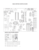
8. The EPROM (CPX.XNMn), in small black ESD box, must be installed in
place of the current EPROM.
9. View the B6000 System Control Board picture on the next page. Note location of
EPROM, U4.
10. Remove four screws holding upper panel with display screen and keypad. Carefully
remove upper panel and turn over exposing B6000 System Control Board, (see next
page).
11. Using ESD procedures carefully remove the EPROM from location U4.
12. Again using ESD procedures carefully install the EPROM labeled CPXXNM or CPXXM
into location U4.
13. Re-assemble B6000 System Control Box.
14. Turn power on to B6000 System Control Box.
15. Connect 120 VAC (hot, Neutral, ground) to T-3 at right terminal block.
16. Re-assemble.