
User Manual
10
Trouble Shooting
Ensure all tests are undertaken by a qualified, trained engineer.
Ensure safe working practices are followed at all times
Step 1: Basics
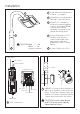
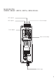
• Check polarity of WHITE-LIGHT Lamp connection
red=+ve, black=-ve
• Check telemetry link is in
• Check photocell is working
• Check power setting pot fully clockwise
• Check mains input
• Check fuse intact
If OK…
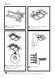
Step 2: Lamp Test
Check voltage of lamp o/p approx 14V
Check current of lamp – see instructions for correct current setting
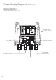
To check lamp current (this must be done while both LED panels
are connected to the PSU) remove +ve LED from both lamp supply
cables and connect multimeter set to 10A current in line with the
lamp. [One lead of multimeter in common (COM), other lead into
10A socket of multimeter; set multimeter to 10A readings]. Refer to
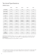
PSU Specications for correct current settings, see pages 7.