Installation and Setup Guide for the VARIO PSU Designed to power all VARIO illuminators (including VARIO IP) VAR-PSU-1x2 (small) VAR-PSU-2x8 (large) VAR-PSU-2x4 (medium) VAR-PSU-3x8 (x-large) Contents Installation Setup VARIO Standard Bracketry VARIO PSU Specifications Troubleshooting
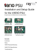
Installation Warnings 1 Select interchangeable lens and mount VARIO illuminator VARIO is factory set and delivered with a 35˚ beam width. To alter to 10˚, simply remove interchangeable holographic diffuser (IHD). To alter to 60˚, replace with other IHD supplied.
4 PSU Connections Connect photocell following output/telemetry if required into ‘Fast Connect’ wiring terminal. Photocell following contact - White & Yellow wires Volt free output. Non polarity sensitive.
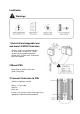
Setup 1 Position illuminator Position illuminator adjacent to camera and point towards scene (Optional night set-up for optimum image performance) 2 Adjust vertical angle 3 Adjust horizontal angle Adjust horizontal angle via Adaptive Illumination (AI) if required (VARIO AI illuminators only) CAUTION: Do not fully loosen AI bolt 4 Tighten all fixings 5 Final illuminator configuration Complete configuration and final setup using VARIO Remote Controller or VARIO IP Integrated Web Interface (or via 3rd part
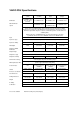
VARIO Standard Bracketry Other bracket options available – see specific illuminator instructions. See VARIO AI Installation instructions for VARIO AI bracketry options.
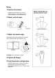
VARIO PSU Specifications VAR-PSU-1x2 (small) Illuminators 1 x VARIO 2 series Plus aux output (max 8w) Other Illuminator options VAR-PSU-2x4 (medium) VAR-PSU-2x8 (large) VAR-PSU-3x8 (x-large) 2 x VARIO 4 series 2 x VARIO 8 series 3 x VARIO 8 series 4 x VARIO 2 series * 4 x VARIO 4 series * 8 x VARIO 2 series * 3 x VARIO 4 series* *Please note: for medium and large PSUs powering an increased number of VARIO illuminators, the total power of the illuminators must be equivalent to the PSU max output
Troubleshooting Ensure all tests are undertaken by a qualified, trained engineer Ensure safe working practices are followed at all times Step 1 Basics Check polarity of illuminator connection: red= +ve, black= -ve Ensure PSU outputs provide 24V DC Ensure telemetry wires are shorted out or closed contact input (zero volt) is applied Check photocell is working. Cover illuminator photocell fully, light should turn on.
Check the LED status indicator on standard VARIO illuminators (not applicable for VARIO IP) – if a flashing red light is visible in programming mode, please check the input voltage of the unit.