
Handheld TV User Manual


r
~
r
CONSOLE
DISASSEMBLY
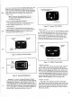
The console
consists of six
separate
subassemblies: the two
halves of
the cabinet,
printed circuit board, two
keyboards,
and a
"Clear"
switch/power-on indicator.
The upper and lower
halves of
the
cabinet are
separated
by
removing
5 Phillips-head screws.
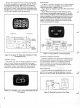
With the bottom
cover
re-
moved, the
underside
of
the printed
circuit board
is exposed.
Lift the
PC
board up at the
cartridge socket
side as shown
in
Fig. 24. This
exposes
the
component side of the
board. The
board
stands on
edge
if set
between pillar
(near "Clear" switch)
and flange of
cabinet upper
half
as
shown.
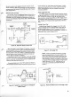
3. Release the keyboard from the
console
by
unlatching
two
brown colored latches as illustrated. Keyboard
is now
free
of
console.
CARTRIDGE
RODE
^
—
"***
^k^===^
'^A
x%
*
\$
"\°
S
V
/
^/^^^^^
"^-^
CART
X^Ss^^
SOCKET
]
\^^
SL0T
TOP
HALF
OF
CABINET
r*
Figure
24. PC Board in
Wiring
Access
Position
NOTE:
The channel-change
and sound
on/off
switches, plug-in cartridge
connector and
other
components mounted
on the PC board
are not
field replaceable.
All PC board
faults (except
speaker)
require board
exchange.
CAUTION:
Tuner sprays containing silicon
must
not
be used on
slide switches.
Irrepairable switch dam-
age will
result.
COMPONENT
REPLACEMENT PROCEDURE
PC Board Removal
Disconnect black, white and
yellow wires from
board; un-
solder coaxial
cable from board
and
carefully
pull
out key-
board
ribbon
leads from RC
board connectors.
See "PC Board
Packing
and
Shipment" for
board exchange
details (Page 14).
Keyboard
Replacement
1.
Keyboard
replacement requires console disassembly as
described above.
2. Unplug
the ribbon cable of the
defective
keyboard from
the
ribbon connector on the
PC
board by
pulling
the
ribbon
straight out
of the connector.
Figure 25. Releasing
Keyboard from
Console
4. Install
new keyboard
by
feeding
ribbon cable through
opening in console before
latching keyboard in place.
5. Push
ribbon cable into connector.
NOTE: Some Studio II units
use
unenclosed
rib-
bon
connectors on PC board. Ribbon
cable must
center in the
connector
so that
all 1
1
leads contact
for proper
operation.
6. If ribbon
cable from keyboard fails
to
make good contact
in connector, trim back
1/16
inch
from edge with
ordinary
household scissors
to
expose
fresh
contact.
Figure
26.
Trim Ribbon
Cable
with Scissors
to
Repair
Damaged
Edge
Coaxial
Cable Replacement
1 . Remove bottom
half of console
cabinet.
Pry off metal
shield covering
end of
coaxial cable.
CAUTION:
Pry
carefully so
as not to damage foil
wiring
on
PC
board.
2. Disconnect cable
by
unsoldering shield first.
Do not
overheat
foil.
3. Install replacement
cable as shown by soldering center
lead first.
4. Re-install
shield
cover carefully
and firmly. Center coaxial
11