
Handheld TV User Manual


Studio
II
Servicing
The recommended
Studio
II service procedure
is to deter-
mine
whether the problem
is in one of
the periphery
components, the
interconnecting
cables or in
the console
itself.
If
the
PC board in
the console
is found
to
be
faulty,
it
must
be
returned to
RCA for
repair on an
exchange
basis.
See Page 14.
IMPORTANT: No
attempt should be
made to
adjust
or repair an
inoperative PC
board
—with
the
exception of
the
clock-frequency
adjustment
described
on Page 13.
As an
aid
to
servicing
Studio II,
a
test
cartridge (see
below)
is available
from RCA.
The cartridge is not
essential to
service
Studio
II; however, it does
provide a
quick and
convenient
means for
isolating malfunctions
in the digital
systems.
When
a
Studio II
comes in for service,
it is
important that
you have
all three assemblies:
Selector Switch Unit,
Power
Supply
Unit and Console.
If the complaint
involves
one or
more
plug-in cartridges,
these
should be
included as well.
SYSTEM
CHECKING
Checking
Studio II
operation can be done
quickly and
easily using
a
test
cartridge
available from
RCA (see
Page
15
for ordering
information).
System
performance
can also be
checked by
operating each
built-in game
function; however,
this
procedure takes more
time than
the test cartridge
check.
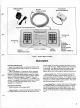
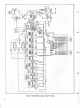
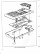
SYSTEM CONNECTIONS
Studio
II connects
to
the
300-ohm
VHF antenna
terminals
of any TV
receiver. Figure 2
describes the
hookup of the three
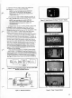
subassemblies. Figures
4,
5
and 6 descirbe
the hookups
with
typical
video-tape machines and
typical
cable TV setups.
Recessed on the underside
of the
console are two
slide
switches
(Fig.
3).
One
switches the game
sound (beeper)
on or
off
while the other changes
operating
channel. Studio
II oper-
ates on TV
Channel 2 or TV
Channel
3 depending
on the
position of the switch.
The switch
should be set on
the unoc-
cupied channel; or
areas where
both
channels are occupied,
on the channel with
the weakest
broadcast
signal. Units
are shipped
from the factory
with the
switch
in Channel 3
position.
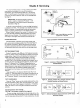
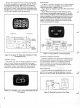
Slide the
switch on
the
Selector
Switch Unit
(Fig.
7)
to
"Studio 1
1".
This
sends power to
the console
(indicated by
the
red
glow of the
pilot light
on
the
console) and
connects
it to
the TV
receiver. Studio
II is now ready
for operation.
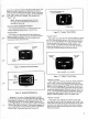
TEST
PROCEDURES
Press the
"Clear" button
on the
console and
press Key 4 on
left-hand Keyboard
A (Key A4).
This sets
Studio
II for "Free-
way" and
the track (Fig.
8)
appears
immediately.
If
necessary,
adjust
the receiver's
fine tuning and
vertical/horizontal
hold
controls.
Operational Checks
Test
Cartridge
(See
Page 7
for
procedure
using
built-in programs).
The test
cartridge, which plugs
into the
cartridge slot on the
Studio II console, scans
the
digital circuitry
for trouble with
a
rou-
tine that
takes about
30
seconds.
If it finds a
malfunction,
the fact
SELECTOR
SWITCH
TO
ANTENNA
\0>
POWER
SUPPLY
*use
75 ohm/300
ohm
matching
transformer
if required.
sj
Figure 2.
Studio
II Connection
Diagram
^J
Figure
3. Locations
of Channel Change
and
Sound
On/Off
Switches
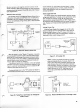
ANTENNA
I
VIDEO
CASSETTE
MACHINE
TWIN
.
STUDIO II
SELECTOR
SWITCH
BOX
TWIN
TV
RECEIVER
LEAD?
LEAD^
^
-^ ANTENNA
/
TERMINALS
sj
Figure 4. Selector Switch Box
Connects
Between
Video
Cassette
Recorder
and
Home
Receiver
CO
-AX
TWIN
TWIN
CATV .
TUNER
STUDIO II
SELECTOR
SWITCH
BOX
TV
RECEIVER
CABLE
LEAD^
LEAo7
^
ANTENNA ,
TERMINALS
Figure 5.
Selector Switch Box
Connects
Between
CATV Tuner
and Home
Receiver