
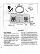
Handheld TV User Manual


r
<**
r
50
ohms
resistance
with
negative
ohmmeter
polarity
on
the
center
conductor.
(With
positive
polarity
on
center
conductor,
resistance
should
be
between
20
and
30k
ohms.)
See
"Coaxial
Cable
Replacement".
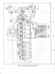
Selector
Switch
Unit Tests
The
quickest
test
for a
troublesome
Selector
Switch
Unit
is
substitution
with a
new
unit
(see
Parts
List).
If
a
new
unit
is
unavailable,
use a
DC
voltmeter
and
ohmmeter to
check
unit
circuitry
(see
schematic
of
Fig. 19)
for
open
or
short-circuited
components.
TWINLEAD
TV SET
CONNECTION
GAME INPUT
TERMINALS
A A
>-9-
(PHONO
J1
JACK)
N
H
TRANSFER
SWITCH
1
O
1-
I 0=
1
o r
J3
TV
ANTENNA
TERMINALS
STUDIO
I
RFC 2
A
A
DC INPUT
TERMINALS
(PHONE JACK)
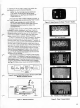
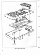
Figure
19.
Schematic,
Selector
Switch
Unit
When
the
switch
is
in the
"Studio
II"
position,
it
connects
the
coaxial
cable
from
the
console to
the
twin
lead and
com-
pletes
the DC
circuit
between
the
console
and
power
supply.
With
the
switch
in
the
"TV"
position,
it
disconnects
the con-
sole
and
forms a
circuit
between
the
antenna
terminals
and
the
twin
lead
for
normal
TV
reception.
If the
Selector
Switch
Unit is
defective,
it must
be replaced
(see
Parts List)
since
it
cannot
be
satisfactorily
repaired in
the
field.
It is
carefully
manufactured
so
as
not
to
exceed
the
RF
radiation
limits
specified by
the
FCC.
If snowy
pictures
occur
in the
"TV"
position
or
Studio
II
cannot be
shut off,
check
antenna
connections
for
short
circuits
to
the
metal box
or
rivets
holding
terminal
board.
If either
antenna
lead
touches
the box
or
rivets,
snowy
pictures
may
result.
(Late
production
units use
insulated
rivets
which
eliminate
problem))
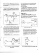
Power Supply
Unit
Tests
The
Power
Supply
Unit
operates
between
carefully
chosen
voltage
and
ripple
limits.
To
check unit
for
satisfactory
opera-
tion,
connect
unit as
shown
in Fig.
20. DC
output
under
these
conditions
ranges
between
8.5
and
10V.
Ripple on
this
DC
(measured
with
oscilloscope)
must
not
exceed
1
V
peak-to-
peak.
Replace
unit if
beyond
these
specifications
(see
Parts
List).
Leakage
Current
Test
With the
Power
Supply
Unit
plugged
into
an AC
outlet,
check
for
leakage
current to
earth
ground
on
both poles
of
the
phone plug,
as
shown
in
Fig.
21 ,
using
an AC
milliam-
meter.
Leakage
current
must not
exceed
0.5mA.
Reverse
AC
plug
polarity
and
recheck
leakage
current.
EARTH
GROUND
Figure
21. AC
Leakage
Test
NOTE:
If
power unit
checks out
OK
but
is inoper-
ative
with
operable
Studio
II console,
check fit
of
plug-in jack.
Some
early
production
plugs
and jacks
have tolerances
that
conflict
and
prevent
adequate
plug
penetration.
Solution to
problem is
often
simply
to
increase
effective
length of
plug by
filing the
jack
slightly as
shown
in Fig.
22. (Use
sharp
knife to
remove
any
untrimmed
mold
flash
from
plug
if
present.)
r
\
-ft-
TO
120V
AC
LINE
ADJUST
FOR
250 mA
ON
MILLIAMMETER
FILE OR
SHAVE
SLIGHTLY
TO INCREASE
PLUG
PENETRATION
—^
Figure
20.
Testing
Power
Unit
Output
for
Voltage
and
Ripple
Content
Figure
22.
Removal
of Material
from
Front Edge
of
Jack