SATELLITE DISH ANTENNA SELF-INSTALLER’S GUIDE
Safety Information DANGER! Avoid Powerlines! When following the instructions in this guide to install and connect the satellite antenna and connections, take extreme care to avoid contact with overhead power lines, lights and power circuits. Contact with power lines, lights, and power circuits may be fatal. CAUTION Before connecting the DSS® receiver, read the Safety Information that came packed with the DSS® receiver.
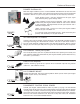
Universal Accessories D940EXP 2nd Room Kit With one digital satellite system, use the D940EXP 2nd Room Kit to view the same programming in another room. And, control your receiver with the Universal Remote included in the kit. Easy to install, your kit includes all the necessary hardware: Signal Sender System - Converts infrared (line of sight) signal into radio frequency (goes through walls).
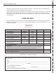
Accessory Order Form To order accessories, contact your local Dealer. If a dealer is not nearby, you can also follow the directions below to order by telephone or by direct mail. To place your order by phone, have your VISA, MasterCard or Discover Card ready and call the tollfree number listed below between 8:00 am and 10:00 pm (EST), Monday thru Friday, or 9:00 am and 5:00 pm (EST), Saturday. USE THIS number only to place an order for the accessories listed on this order form.
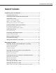
Connections and Setup Table Of Contents Preparing for Installation ................................................ 3 Installation Overview ................................................................... 4 The Big Question: Should I Do This Myself? ................................ 5 General Site Survey ...................................................................... 5 Finding a Clear Line of Sight ...................................................................
Table of Contents Final Installation ........................................................... 27 Leveling the Mast ....................................................................... 28 Leveling Side-to-Side ............................................................................. 28 Leveling Front-to-Back .......................................................................... 29 Final Dish Assembly ..................................................................
Preparing for Installation There are a few tasks you need to complete before you will be ready to mount the satellite dish, the most important of which is to make sure you have a clear line of sight to the satellite.
Installation Overview Installation Overview The manual is organized into steps that need to be performed in the order presented. Preparing for Installation • Complete a General Site Survey – Visually survey your location to make sure it is suitable. • Obtain Dish Pointing Coordinates – Use the on-screen menu system to obtain the exact coordinates (azimuth and elevation) for pointing the dish. Directions for using on-screen menus can be found in your receiver manual.
General Site Survey The Big Question: Should I Do This Myself? While the installation is not difficult, it does require that you have some experience in electrical wiring and minor construction techniques. Also, you may have to climb a ladder, so you’ll want to be comfortable working with heights.
General Site Survey Where Is The Satellite, Anyway? The satellite is always located south of Texas. That means if you live in Miami, you must have a clear line of sight to the southwest; if you live in San Francisco, you must have a clear line to the southeast. How High Up in the Sky is the Satellite? Depending on where you live, the satellite will be at an elevation angle between 30 and 60 degrees. Southern states point more toward 60 degrees; northern states point more toward 30 degrees.
Finding the Dish Pointing Coordinates Finding the Dish Pointing Coordinates You need to connect the satellite receiver to your TV and use the on-screen menu system to find the dish pointing coordinates for your location. Connecting the Receiver to a TV Additional Information This example shows a basic connection. Refer to the manual that accompanies the receiver for additional connection options. For this task, you use the most basic connection to save time.
Finding the Dish Pointing Coordinates Using the Dish Pointing Menu Screen The satellite receiver has an on-screen menu feature for obtaining the precise dish pointing coordinates for your location. You can use the buttons on the front panel of the receiver to navigate through the menu system, or you can use the remote control. If you have not already inserted batteries into the remote, you can do that now. Directions for using on-screen menus can be found in your receiver manual.
Precise Site Survey Precise Site Survey Based on your general site survey, you probably already know where you want to mount your dish, but it’s a good idea to follow the procedures outlined in this section in order to make sure that your site selection is a good one. 1. Go outside to your install site and hold a compass flat in the palm of your hand. Hold your hand still until the needle stops moving (the dark or colored half of the compass needle always points north).
A Final Site Survey ,, ,,, ,,, Now that you’ve conducted a precise site survey using the dish pointing coordinates for your location, you should double-check one more time to make sure you have a clear view to the satellite. 60° 30° NO I Don’t have a clear view to the satellite. If you don’t have a clear view to the satellite, then your site may not be suitable for installing the satellite system.
Estimating Cable Requirements Estimating Cable Requirements Now that you’ve decided on the exact mounting site, you need to decide where you want the cable to enter the house, and then figure out approximately how much cable you are going to need. The diagram below shows you a “typical” installation scheme, outlining the cables that are needed. The information on the following page takes you through the cable estimating process step-by-step.
Estimating Cable Requirements Cable Estimate Procedure Tip 1. Locate the central building ground. You will ground the dish (via the cable grounding block) to a single point in the central building ground. The following is a list of acceptable building ground points: • Grounded interior metal cold water pipe within five feet of the point where it enters the building. • Grounded metallic service raceway. • Grounded electrical service equipment enclosure.
Dish Assembly Overview Dish Assembly Overview Use this page both as a parts lists for your satellite antenna, and a general overview of how the parts fit together; but DON’T ASSEMBLE THE DISH YET.
Partial Dish Assembly Partial Dish Assembly 1. Locate the reflector, the support arm, and the hardware packet. 2. Attach the reflector to the support arm : • Metal Reflector: Pass the bolts through the reflector, and then place the reflector on the support arm by inserting the bolts through the holes on the support arm. Use a wrench to secure the four self-locking nuts. • Plastic Reflector: Pass the four bolts molded into the back of the reflector through the four holes on the support arm.
Mounting the Mast Now that you have selected your site, and estimated your cable needs, you need to select a mounting option and mount the mast. Take a moment to look through the available options and select the one that best suits your installation site. After you have selected a mounting option, and successfully mounted the mast, you can go on to the final section of this manual to complete the installation.
Mounting the Mast on Solid Wood or Lap Siding Mounting The Mast On Solid Wood Or Lap Siding Materials Needed Tools Needed • Electric drill with a 3/16" wood bit • Bubble level 2 5/16 x 3" lag screws • 1/2" wrench • 3/8" wrench • 7/16" wrench • Pencil 4 4 5/16 x 5/16" 2" lag screws washers Important Considerations: • Make sure the wooden surface is structurally sound • Do NOT mount the dish where someone might use it as a handrail.
Mounting the Mast on Solid Wood or Lap Siding Tip Mounting Instructions 1. Locate the center of a stud where you want to mount the mast foot. Make sure you locate and secure the mounting foot to the center of a wall stud. Do not mount the dish near the edge of a stud. To locate a stud underneath panel siding, locate the nails securing the panel to the wall. The nails usually align with the center of the stud and provide an easy guide. 2.
Mounting the Mast on Solid Wood 8. Install two 5/16" x 3" lag screws into the two center holes on the mounting foot. Securely tighten the screws. 9. Put washers on the 5/16" x 2" lag screws, insert the screws into the four outside holes and securely tighten them. 5/16" x 2" Lag Screws 5/16" x 3" Lag Screws (For Sony Dish Installations use (2) 3" x 1/4" Lag Screws) 5/16" x 2" Lag Screws Steps 8 & 9: Inserting the lag screws. 10.
Mounting the Mast on Brick or Poured Concrete Mounting the Mast on Brick or Poured Concrete Materials Needed Tools Needed • Electric drill with 1/2" masonry bit • Bubble level 4 double expansion anchors • Screwdriver • Hammer • 7/16" wrench • Pencil 4 machine screws 4 5/16" washers IMPORTANT Considerations • The wall anchors used must have a strength of at least 300 pounds of pull-out pressure. B4015 or equivalent doubleexpansion anchors are recommended.
Mounting the Mast on Brick or Poured Concrete 5. Insert four (4) double-expansion anchors. 6. Use a wrench to loosen the nuts on the mounting foot so you have easier access to the mounting holes. 7. Hold the mounting foot over the holes so the top part of the mast will rotate and point straight up. Yes No Step 7: Make sure that the top of the mast will point straight up. 8. Insert and tighten the machine screws. 9. Go on to the next section, “Final Installation,” to complete the installation process.
Mounting the Mast on a Hollow or Cinder Block Wall Mounting Instructions DANGER 1. When installing togglers in cinder blocks, it is important to position them in the core of the block. To position the foot on the wall, measure 7-1/2" from one edge of the block and mark the center of the block. 2. Center the mounting foot on the mark you made. 3. Level the center line of the mounting foot using a bubble level.
Mounting the Dish on a Hollow or Cinder Block Wall ,, ,, , ,, , c. Push the straps side-to-side to snap them off flush with the wall. Step 6c: Snap off straps flush with the wall. d. Repeat for all four holes. 7. Use a wrench to loosen the nuts on the mounting foot so you have easier access to the mounting holes. No Step 8: Yes Make sure that the top of the mast will point straight up. 8. Hold the mounting foot over the holes so the top part of the mast will rotate and point straight up. 9.
Mounting the Dish on a Pole Mounting the Dish On A Pole Materials Needed Tools Needed • (1) 1-1/4" inner diameter Schedule 40 galvanized steel pipe with a measured outer diameter of 1.6" • Bubble level • (3) bags quick-setting concrete • Screwdriver • Hammer • Hacksaw • Shovel or post hole digger • Pencil Important Considerations: • Do not install the pole in wet or marshy areas. • The pole must go at least 3 feet below the surface.
Mounting the Dish on a Pole 2. Use a hacksaw to cut a 45o angle at the bottom of the pole. This will prevent the pole from rotating in the concrete over time. 45° cut 3. Place the pole in the hole and use a small amount of dirt or stones to hold the pole upright. You need to attach guy wires to help keep the pole upright. 4. Level the pole using the bubble level. Level the pole at two different locations that are at right angles to each other.
Mounting the Mast on a Roof Mounting the Mast on a Roof IMPORTANT Use the roof mount only as a last resort. You can easily damage the roof by walking on it or cause leaks by not properly sealing the mounting holes. Problems with roof installations increase with the age of the roof and the type of roofing materials.
Mounting the Mast on a Roof 2. Hold the mounting foot in a position so the center line is centered on a rafter. 3. Use a bubble level to make sure the center line is perfectly vertical. Level on center line of template Level Not Level Steps 2 & 3: Center the mounting on a rafter and make sure that it is level. 4. Use a pencil to mark the six holes in the mounting foot. 5. Remove the mounting foot and drill a 3/16" hole in the two center line locations you marked. 6.
Final Installation This section contains the final steps necessary to get the signal from the satellite dish to your satellite receiver.
Leveling the Mast Leveling the Mast Leveling the mast is one of the most important steps in installation. If the mast is not level, the elevation and azimuth settings will not be accurate. This will make it difficult to obtain the satellite signal. The mast must be level in both the side-to-side and the front-to-back directions. Side-to-side leveling determines whether the mounting foot is level. Front-to-back leveling determines whether the mast is level. Leveling Side-to-Side 1.
Final Dish Assembly Leveling Front-to-Back 1. Loosen the two bolts securing the mast to the mounting foot so the mast moves freely. 2. Place a bubble level on the mast as shown in the figure. Move the mast so the bubble is centered in the level’s window. Level Level Not Level Not Level Rotate mast as needed Rotate mast as needed Adjustment Adjustment Step 2: Verify that the mast is level front-to-back. 3. Tighten the two bolts securing the mast to the mounting foot. Final Dish Assembly 1.
Final Dish Assembly 3. Separate the messenger (ground) wire from the coaxial cable. Separate only the amount required to install the coaxial cable through the LNB arm. (Sony dish owners skip to next step.) Push only the coaxial cable through the bottom of the mast and out the top. Pull about 2 feet of cable out of the top. Loop the cable and push it through the LNB support arm as shown below. 4. Place some silicone grease on the LNB connector and connect the end of the coaxial cable to the LNB.
A Few Words About Grounding the System A Few Words About Grounding the System Grounding the satellite system to the central building ground helps protect it and other components from lightning damage. Different brands of satellite systems may have special grounding requirements. However, dish installation should comply with local codes and the National Electrical Code (NEC). Refer to your satellite system’s user guides for any other additional grounding information.
Routing and Grounding the Cables 2. Route the coaxial cable and messenger (ground) wire from the bottom of the mast to the grounding block. 3. Make a 3”- 5” drip loop using cable clips at the grounding block as shown. This will prevent water from running into the connection at the grounding block. 4. Place some silicone grease on the connector and connect the coaxial cable to the grounding block 5. Secure the messenger (ground) wire to the grounding block,. 6.
Running a Cable into the House Running Cable Into the House 1. Drill a hole in the location you want the coaxial cable to enter. 2. Place some silicone grease on the connector and connect the RG-6 coaxial cable that will extend from the grounding block to the receiver. 3. Make a 3” - 5” drip loop using cable clips at the grounding block. 4. Route the coaxial cable through your house to the back of the receiver. You may route the coaxial cable through a floor or wall or directly to the back of the receiver.
Making the Final Connections Making the Final Connections 1. Connect the RG-6 coaxial cable to the SATELLITE IN jack at the back of the receiver as shown. DO NOT connect the coaxial cable to the IN FROM ANTENNA jack! 2. Take a phone off the hook to prevent electric shock from incoming calls. 3. Connect a phone cord from the back of the receiver to a phone jack. Step 1: Connect the RG-6 cable to the SATELLITE IN jack on the back of the receiver.
Acquiring and Fine Tuning the Signal Now that you have installed the satellite antenna and routed all of the cable, it’s time to acquire and fine tune the signal. Before you begin, you may want to go outside and double-check the azimuth and elevation settings on the dish. • Make sure that the elevation indicator (the edge of metal, not the washer or the bolt) is aligned to the correct elevation. • Use a compass to verify that the azimuth setting on the dish is correct.
Acquiring and Fine Tuning the Signal Adjusting the Azimuth and Elevation Settings 1. Using a compass, rotate the dish so that the LNB arm points to the correct azimuth heading. Loosen the support sleeve nuts as needed. (Sony dish owners loosen the mast clamp screws.) Point LNB arm in the exact azimuth direction according to your compass Support Sleeve Nuts 2.
Acquiring and Fine Tuning the Signal 6. Slightly loosen the elevation nuts on the LNB support arm so you can adjust the dish up and down. 7. Adjust the elevation of the dish upward and downward until you achieve the highest possible signal strength: Use the edge of the metal here to line up the elevation Do not use this to line up the elevation Elevation Adjustment When setting the elevation, be sure to line up the elevation setting with the elevation indicator and not the bolt.
Troubleshooting Troubleshooting Can’t Pick Up the Satellite Signal Most problems with signal acquisition can be traced to one of these points: improper cabling and connections or inaccurate positioning and pointing of the dish. Cabling and Connections Problems 1. Make sure you’re using the proper type of RG-6 coaxial cable to connect the LNB to the grounding block and the grounding block to the satellite receiver. Standard Cable TV coaxial cables (RG-59) will NOT pass the satellite signals properly.
Troubleshooting Temporary Satellite Signal Loss If you lose the satellite signal temporarily, the problem can usually be traced to one of these points: 1. Rain Fade. Rain fade is a normal, temporary loss of a satellite signal due to the inability of the satellite signal to penetrate unusually heavy, rain-filled clouds, rainfall, or snowfall. Rain fade tends to be brief, lasting only as long as the heavy cloud condition persists. To minimize rain fade effects, maximize your signal strength.
Troubleshooting Digital Satellite System Installer's Reference Thomson Consumer Electronics (Digital Satellite Systems) Support Line Digital Satellite System Service Support Line 1-800-679-4776 Call this number to resolve service and use and care questions. Program Providers DIRECTV Customer Service 1-800-347-3288 Use this number to resolve programming and billing inquiries and to deactivate service. Installer Activation 1-800-277-4388 Use this number to activate a newly installed system.
Index Index A G P Acceptable central building ground points 31 Acquiring the satellite signal 35 Azimuth setting, adjusting 36 Ground wire, separating 30 Grounding block 12 Grounding the system house entry point 31 Grounding wire 32 Phone connection 34 Plastic dish putting together 14 Precise site survey 9 C R Cable, routing into the house 33 through the mast 30 Central building ground 11, 31 acceptable points 31 CH3/CH4 switch 7 Compass, using 9 Connecting the dish to the receiver 34 L D Mast,
10330 North Meridian Street Indianapolis, IN 46290 ©1998 Thomson Consumer Electronics, Inc.