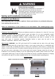
* Installer: Leave this manual with the proud new owner * Also be sure to check the grill box completely for ALL parts including the rotisserie spit rod (if applicable) Renaissance Cooking Systems Owner’s Manual For Outdoor Use Only America's Best Value in Outdoor Kitchen Equipment Installation, Operation, Maintenance Instructions & Parts List Models: RJC26A, RJC32A, RJC32AL, RJC40A, RJC40AL, RON30A, RON38A & RON42A These grills are tested and certified to the ANSI-Z21.58/CSA 1.6.standards.
Contents For Your Safety Safety Rules First Time Operation Gas Barbecue Specifications BTU Ratings LP Tank Requirement Clearance to Combustibles Installation Location/Cut Outs Gas Connections Electrical/Wire Diagram Burner Adjustments Lighting Instructions Operation Cleaning and Maintenance Gas Conversion /Trouble Shooting Troubleshooting Parts Diagram Warranty Page 3-7 8 9 10-11 11 11-12 13 13-15 16-17 18-19 20-21 21 22 23 24-26 26 27-32 33 Message to the Proud Owner Congratulations on the purchase of th
Safety and Installation Instructions GRILL INSTALLATION This gas grill must be installed in accordance with all local codes. If installation is planned in an area with no local codes, the gas grill must be installed in accordance with the National Fuel Gas Code ANSI Z223.1 and storage and handling of liquefied petroleum gases, ANSI/NFPA 58 or CSA B149.1 natural gas and propane installation code.
FOR YOUR SAFETY 1. Do Not store or use gasoline, caustic or other flammable vapors and liquids in the vicinity of this or any other appliance. 2. An LP cylinder not connected for use shall not be stored in the vicinity of this or any other appliance.. TESTED IN ACCORDANCE WITH ANSI STANDARD FOR OUTDOOR COOKING GAS APPLIANCES. THIS GRILL IS FOR OUTDOOR USE ONLY. Check your local building codes for the proper method of installation.
Do not use the grill as storage area for flammable or caustic materials. Keep area clear and free from combustible, gasoline, swimming pool chemicals, and other flammable vapors and liquids. Failure to do so can result in death, explosion, or fire. Safety and Installation Instructions Location of your Barbecue Most importantly, this is an outdoor appliance. Ensure your barbecue is positioned safely away from anything that can catch fire. Under no circumstances is this barbecue to be used indoors.
Adequate Ventilation: Ensure there is adequate ventilation for both the barbecue, cylinder and all appliances located in this cabinet. Adequate ventilation is required for proper combustion and to prevent gas build up. Kitchen vents (RVNT1) are required every 4 feet to help ventilate and prevent dangerous gas build up, remove excess heat, add air to help with air/fuel mix for the grills and allows moisture/ condensation to evaporate.
|Page
Safety Rules • It is important to follow these rules to avoid fire hazard, property damage or bodily injury from improper installation or usage of the grill. For safety, READ all rules carefully and check local codes. • It is prohibited to install the grill in recreational vehicles/mobile homes, trailers, boats, etc. The grill is for outdoor installation and use only. • Ensure proper installation by following the installation instructions. Make sure to know where the gas supply shut-off valve is located.
First Time Operation Your RCS Appliance comes per-assembled and requires very little setup. We do however; recommend the use of professional help during the installation of your unit as improper installation may affect your warranty. Remove the unit from the box along with all accessories and check that no damage has occurred to the unit or any parts. Remove all packaging materials, labels and protective plastic film before you start cooking.
Gas Connections Check gas type – use only the type of gas indicated in the rating plate. -The rating label is located on the left or right hand outside of the unit. RATING PLATE LOCATION DO NOT connect high pressure to this grill. This grill uses low pressure 1/2" psi to operate. You MUST use the regulator(s) that are available from RCS. An intermediate (stepdown) regulator may be necessary. Check with your gas supplier if you are not sure.
GAS BARBECUE SPECIFICATIONS BURNER INPUT RATING Grill Model RJC26A RJC32A / RJC32AL RJC40A / RJC40AL RON30A RON38A RON42A Main Burners 12,000 12,000 12,000 15,000 15,000 15,000 Rear Burners Total BTU’s 12,000 12,000 12,500 12,500 12,500 36,000 60,000 72,000 57,500 72,500 72,500 Natural Gas Connection: Appliance pressure Inlet pressure 4” W.C. 5” – 14” W.C. Check with your local gas utility company or with local codes before installing gas lines.
To connect, insert the regulator inlet into the tank valve and turn the black coupler clockwise until the coupler tightens up. DO NOT OVER TIGHTEN THE COUPLER. After completion of assembly, make sure all appliance control valves are OFF then turn the propane tank supply valve on and then turn the control valves on the grill to the ‘HI/IGN’ position for approximately 5 seconds to purge the line of air out of the gas line. After 5 seconds, you may turn on the other burners.
Installation Location for All Models Choose a location where the flow of air on the front or rear of the grill is not obstructed. Due to high temperatures, place the grill out of traffic and keep away from clothing, furniture, or any combustible materials. Keep the gas line connection as short as possible. Do not install in recreational vehicles/mobile homes, trailers, boats, etc. A minimum of five(5) foot clearance is required between the counter top and the overhead noncombustible construction.
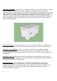
Model/Part Number RWGM - RJC26A/RJC32A/RJC32AL/RON30A BEFORE RWGL - RJC40A/RJC40AL/RON38A/RON42A AFTER Built-in Installation For non-combustible cabinet enclosure installation only. Follow the cut-out dimensions as shown. ALL outdoor kitchen cabinets MUST include ventilation. There must be 12 square inches of opening for each (running) 4 feet of counter top. See Item # RVNT1 for approved vents.
“A” Width “B” Depth “C” Height RJC26A 23 1/2” 21” 8 ¼” RJC32A /RJC32AL 30 5/8” 20 3/4” 8 ¼” RJC40A / RJC40AL 37 3/4” 21” 8 ¼” RON30A 33” 20” 11” RON38A 41 1/4” 20” 11” RON42A 45” 20” 11” Model REAR HOOD CLEARANCE Hood Clearance RJC26A 25” RJC32A / RJC32AL 25” RJC40A / RJC40Al 25” RON30A 23” RON38A 23” RON42A 23” Model Notch Cut Outs for Appliance Control Panel 15 | P a g e Note: these notch dimensions above refer to the width (left to right) not depth of the cut.
Exhaust Hood Requirements When using an exhaust hood, the area above the cooking surface of the grill must be covered with a hood larger than the cooking area of the grill, AND with a minimum of 1200CFM (cubic feet per minute) for proper outdoor application. Combustible Overhead Construction: Exhaust hood required. Non-Combustible Overhead Construction: Exhaust hood recommended.
If adding a side burner to your connection: Electrical Electrical outlet for Rotisserie motor must be installed to the left side of the grill. The outdoor cooking gas appliance, when installed, must be electrically grounded in accordance with local codes or, in the absence of local codes, with the National Electrical Code, ANSI/NFPA 70, or the Canadian Electrical Code, CSA C22.1. Keep any electrical supply cord and fuel supply hose away from any heated surface.
Cutlass Pro Electrical Wire Diagram 18| P a g e
Premier Series Electrical Wire Diagram Connector Black White Connector Black Red White LED Switch Red Black White White Black Connector RJC32AL 5 LEDS 2 HALOGEN LIGHTS RJC40AL 6 LEDS 2 HALOGEN LIGHTS 19 | P ag e
Leak Testing NEVER USE AN OPEN FLAME TO CHECK FOR LEAKS. All gas piping and connections must be tested for leaks after installation or service. All leaks must be corrected immediately. Remember-before exchanging an empty bottle for a new one, make sure all control valves are in the “off” position. With the LP regulator connected to tank and grill and the grill knobs turned to OFF. Open the valve on the tank. Test for leaks by applying liquid soap solution to all joints. Bubbles forming indicate gas leak.
If flame is lifting, remove the front panel to access the burner front (air shutter) then turn the air shutter clockwise reducing this intake. The screw should be loosened before turning the air shutter. If the flame has more yellow than blue, the air shutter should be turned counter clockwise allowing more air in. This will stabilize the flame. Make sure to tighten the screw after adjustments are made. In order to provide gas to the burner, the orifice must be inside the burner venturi opening.
Optional Infred Burner 1. To install the optional infrared burner, begin by removing the far left cooking grid, flame tamer and zone divider, if applicable. 2. Remove conventional burner by first removing the cotter pin or screws that hold the burner in place (unless they were removed prior to installation), located on the bottom rear of the burner and located inside the rear of the grill body.
Cleaning and Maintenance Cleaning: Your grill works better and lasts longer if properly cleaned and maintained. Clean the grill after each use. Turn grill off before starting to clean. Protect your hand with a good mitt when cleaning the hot grill. Use a wire brush, dip in water and scrub the cooking grids to soften and loosen food spills. The food spills will fall into the crumb pan. Burn off excess food debris and marinades for 15 minutes after cooking. Do not use Aerosol cleaners on hot grill surface.
Important Note: For Locations Near Coastal Areas and Pools #304 stainless steel materials used in the construction of your cutlass PRO series grills are highly rust resistant, however, chlorine in the air from swimming pools or the salt from sea air may cause surface rust to appear and even create some pitting if left on the product.
Fuel Conversion of Main Burners: 1- Determine the existing gas type (LP or Natural gas). The method of changing gas types is similar for natural gas or propane gas. 2- You must remove all grates and burner covers to expose the main burners in the grill. 3- On the bottom rear of each burner may be a cotter pin or screws attaching burners to the grill housing. Remove cotter pins or screws. 4- Slide burner to the rear of the grill and up. Repeat for each burner.
Rotisserie Burner Conversion: 1- Remove the back panel at the rear of the grill, this will expose the V shaped or pyramid shaped brass orifice. 2- Replace with new orifice. 3- Replace rear panel. Trouble Shooting: Problem and Solution Burner will not light • Check gas supply to burner by manually lighting the burners. • See electrode for visible damage, replace if damaged. Improper Burner Flame • Check burner gas inlet area for blockage • Check orifice hoods for any clogging and clean.
RJC26A/RJC32A/RJC40A Enlarged View 27| P a g e
RJC26A/RJC32A/RJC40A Parts List ITEM PART NO.
RJC32AL / RJC40AL Enlarged View 29 | P a g e
RJC32AL/RJC40AL Parts List ITEM PART NO.
RON30a/RON38a/RON42a Enlarged View C) 31 IP age c·
RON30a/RON38a/RON42a Parts List QTY. QTY.
Renaissance Cooking Systems Product Warranty RCS is proud to provide the industries most comprehensive warranty program. All RCS Cutlass Pro Series Grills, Cutlass and Cutlass Pro side burners, Valiant doors and drawers are now warrantied to be free from manufacturer defects for the lifetime of the original owner. All RCS Premier Series Grills and side burners are warrantied to be free from manufacturer defects for 15 years to the original owner.