
Owner manual


2
Always read the owners manual before using the equipment
Keep the owners manual in a place where you can easily find it
The amplifier is only for in-vehicle operation
Never use the equipment in the vicinity of heat source and/or in direct sunlight
Make sure that no small objects or liquids can get into the amplifier
Negative bettery terminal must be disconnected before any electrical connections
are made
•
•
•
•
•
•
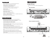
WIRING INSTRUCTIONS
The battery terminal(+12V) must be connected directly to the positive terminal of the
vehicle’s battery to provide an adequate voltage source and minimize noise. Connecting
the battery terminal lead to any other point(such as the fuse block) will reduce the power
output and may cause noise and distortion. Use only 8 AWG or thicker(smaller AWG) wire
for this lead and connect it to the terminal of the battery after all other wiring is
completed.
Power Connection
The ground terminal(GND) connection is also critical to the correct operation of the
amplifier. Use a wire of the same gauge as the power connection(8 AWG or thicker) and
connect it bwtween the ground terminal(GND) of the amplifier and a metal part of the
vehicle close to the mounting location. This wire should be as short as possible and any
paint or rust at the grounding point should be scraped away to provide a clean metal
surface to which the end of the ground wire can be screwed or bolted.
Ground Connection
The amplifier is turned on by applying +12V to the remote turn-on terminal(REM).
The wire lead to this terminal should be connected to the “Auto-Antenna” lead from the
head unit. If the head unit does not provide an “Auto-Antenna” lead, the remote turn-on
lead may be wired to an “Accessory” or “Radio” terminal in the vehicle’s fust block. This
will turn the amplifier on or off with the ignition key regardless of whether the head unit
is on or off. The remote turn-on lead does not carry large currents. So 20 AWG wire may
be used for this application.
Remote Turn-on Connection
Depending on the type and number of speakers, connect them to the speaker terminals
as shown in the appropriate wiring diagram. For most applications, 16 AWG wire would be
adquated, but in no case thinner than 18 AWG. For leads more than 10 feet long, 14 AWG
is recommended. When wiring the speakers, pay special attention to the polarity of the
terminals. Do not gournd any speaker leads to the chassis of the vehicle.
Speaker Connection
READ FIRST!
It is our recommendation that all RE Audio products should be installed by an autho-
rized dealer.
9
SPECIFICATIONS
Power Output (RMS)
Total Harmonic Distortion
S/N Ratio
Channel Separation @
4Ω RMS
Power Band Width (Frequency Response)
Crossover Frequency
Bass Boost Control @ 45Hz
Damping Factor
Wired Remote Control
Gain Control
Dimensions [(L) in/mm] (W)8.66/220 x (H)1.93/49
Fuse Rating
Protection (
thermal, overload, short circuit, DC offset)
Power Voltage Range
Input
Sensitivity
Input Impedance
4Ω
4Ω
4Ω mono
2Ω
1Ω
Input Short
Low Pass
Low Level
High Level
Subsonic
High Pass
4Ω
@ 14.4V
100Hz
1KHz/100Hz
1KHz/100Hz
1KHz/100Hz
-3dB
24dB
24dB
12dB
mV/V
in/mm
A
V
V
W
W
W
%
dB
Hz
dB
KΩ
Hz
Hz
Hz
2 x 80
2 x 60
<0.02
100
10~50K
22
8.27/210
25A x 1
50~250
50~250
0~12
—
Yes
Yes
11~15V
200
6
—
600.2 750.4
4 x 60
4 x 80
——
2 x 160 — —1 x 160
<0.02
100
10~50K
22
12.2/310
40A x 1
50~250
50~250
0~12
—
180180
Yes
Yes
11~15V
200
6
—
1600.1
1 x 550
1 x 350
1 x 750
< 0.05
100
10~250
22
11.42/290
40A x 2
35~250
—
0~18
180 180
Yes
Yes
Yes
11~15V
200
6
10~50
2000.1
1 x 700
1 x 430
1 x 1000
< 0.05
100
10~250
22
12.2/310
40A x 3
35~250
—
0~18
Yes
Yes
Yes
11~15V
200
6
10~50
* Specification subject to change without notice