
Datasheet

www.recom-power.com
REV.: 5/2018 I-4
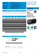
DC/DC Converter
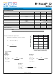
Specifications (refer to standard application circuit, Ta= 25°C)
R-7xxxP_D
Series
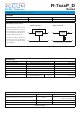
REGULATIONS
Parameter Condition Value
Output Accuracy full load ±1.0% typ. / ±2.0% max.
Line Regulation low line to high line, full load ± 0.5% typ. / ±1.0% max.
Load Regulation
(5)
10% to 100%, full load ± 0.5% typ. / ±1.0% max.
Transient Response
(6)
50% load step change
Vout Over / Undershoot
100µs typ. / 200µs max.
100mV max.
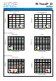
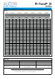
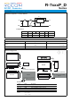
2ADC R-723.3P/D R-725.0P/D R-726.5P/D R-729.0P/D R-7212P/D R-7215P/D
3ADC R-733.3P/D R-735.0P/D R-736.5P/D R-739.0P/D R-7312P/D R-7315P/D
4ADC R-743.3P/D R-745.0P/D R-746.5P/D
Vout nom. 3.3VDC 5.0VDC 6.5VDC 9.0VDC 12VDC 15VDC
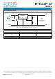
Vout adj.
R1 R2 R1 R2 R1 R2 R1 R2 R1 R2 R1 R2
2.5 8.5kΩ
3.0 33kΩ 470kΩ
3.2 110kΩ 1.6kΩ
3.3 2.2kΩ
3.4 36kΩ 3.0kΩ
3.6 11kΩ 4.7kΩ
3.9 4.7kΩ 8.5kΩ
4.5 1.6kΩ 30kΩ
4.9 820Ω 220kΩ
5.0 680Ω 11kΩ
5.1 560Ω 28kΩ 12kΩ
5.5 190Ω 2.6kΩ 20kΩ
6.0 47kΩ
6.5
7.0 4.5kΩ 13kΩ
7.5 2.2kΩ
8.0 31kΩ
9.0
10 2.2kΩ 20kΩ
11 390Ω 47kΩ
12
13 2.4kΩ 36kΩ
14 390Ω 76kΩ
15
16 2.6kΩ
17 860Ω
Trim Table
Notes:
Note5: Operation below 10% load will not harm the converter, but specifications may not be met
Note6: Requires a 100µF electrolytic or tantalum output capacitor for proper operation in all applications
(the capacitor has to be placed as close as possible to the output pins)