In-vehicle 3-Stage 24V Battery Charger BCDC2420 & BCDC2420-LV
THE BCDC2420(-LV) The BCDC2420(-LV) In-vehicle Battery Chargers feature technology designed to charge your lead-acid batteries to 100%, regardless of their type or size. By providing a unique charging profile to each specific battery type, the BCDC2420(-LV) In-Vehicle Battery Chargers are able to achieve and maintain an optimal charge in your auxiliary battery, at all times.
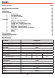
CONTENTS Table of Contents Page Warnings and Safety Instructions Contents Specifications 1 Product Function 1. Display Panel 2. Charging Algorithm 3. Turn On/Off Thresholds 4. Error Codes 2 Installation 1. RED wire - Input Source Positive 2. BLUE wire - Source Select 3. ORANGE wire - Charging Profile Select 4. BROWN wire - Auxiliary Battery Positive 5. BLACK wire - Common Ground 6. GREEN wire - Optional External LED Indication 7. Cable Sizing 8. Wiring 9.
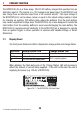
1 PRODUCT FUNCTION The BCDC2420(-LV) is a three-stage, 24V DC-DC battery charger that operates from an alternator input of 12V nominal or a 12V nominal solar panel input. The BCDC2420 will also charge from an alternator input from a 24V nominal vehicle*1. The input voltage of the BCDC2420(-LV) can be above, below or equal to the output voltage making it ideal for charging an auxiliary 24V battery bank where the distance from the main battery may cause a significant voltage drop.
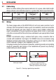
1 PRODUCT FUNCTION 1.2 Charging Algorithm When the BCDC2420(-LV) is turned on, it will move into the Boost stage. The Boost stage maintains a constant current until the battery voltage reaches the Absorption Voltage. The current during Boost stage may vary throughout operation in order to maintain a safe operating temperature, or to limit the difference between input and output voltages.
1 PRODUCT FUNCTION 1.4 Error Codes In the event of a fault with the unit installation, either battery or solar panel, ALL the LEDs on the unit will flash to indicate the fault type. Flashing sequences are described in the table below. LED State Description 1 flash (1 flash followed by 3.5 second off) Internal Hardware Fault 2 flash (2 flash followed by 3.5 second off) Reserved 3 flash (3 flash followed by 3.5 second off) Unit over temp fault 4 flash (4 flash followed by 3.
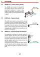
2 INSTALLATION 2.2 BLUE wire - Source Select The BLUE wire is provided to select whether the unit is charging from a vehicle input or from a solar panel. This wire is monitored at all times. For standard (non ‘LV’) models, the BLUE wire may be permanently connected to the Input Source Positive supply and the charger will only charge when the alternator is running. This is not suitable for the BCDC2420-LV.
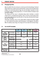
2 INSTALLATION 2.3 ORANGE wire - Battery Type Select The ORANGE wire is used to select the Maximum output voltage. This is achieved by connecting in the following way: Not Connected To select Profile A leave the ORANGE wire disconnected. This will set the Maximum voltage to 29.2V. To select Profile B connect the ORANGE wire to Common Ground. This will set the Maximum voltage to 30.0V. To select Profile C connect the ORANGE wire to the RED wire (Input source positive).
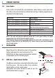
INSTALLATION 2.4 BROWN wire - Auxiliary Battery Positive The BROWN wire should be connected to the auxiliary battery’s positive terminal. This should be a maximum of 1 metre in cable length from the battery. Appropriate size fuses should be used as per the specifications table on page 2. 2.5 Auxiliary Battery BLACK wire - Common Ground The BLACK wire should be connected to a ground point that is common to both the Start battery (or the Solar Input Ground wire) and the Auxiliary battery to be charged.
2 INSTALLATION 2.7 Cable sizing Below is a table outlining the required cable size for a given cable install length. Always choose a wire diameter equal to or greater than what is specified below. Part Number Cable Install Length (m) Recommended Wire Size (mm²) Closest (BAE, B&S, AWG) BCDC2420(LV) 1-5 5-9 13.56 20.28 6 4 2.
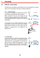
INSTALLATION BCDC2420 Optional LED 12V OR 24V INPUT Brown Green Red Blue Orange Black INPUT Loads 30A Fuse Fuse* Load Fuse 24V Charging Profile Select Refer to section 2.3 Start Battery Auxiliary Battery All ground points must be connected to chassis earth. *Fuse Ratings as per table on Page 2 Figure 2.
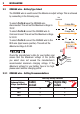
2 INSTALLATION BOTH MODELS Optional LED SOLAR INPUT 12V Solar Panel Array Brown Red Blue Orange Black Green Loads 30A Fuse Load Fuse Charging Profile Select (Refer to section 2.3) Auxiliary Battery All ground points must be connected to chassis earth. *Fuse Ratings as per table on Page 2 Figure 2.
2 INSTALLATION 2.9 Fusing REDARC recommend using MIDI style bolt down fuses as they ensure a low resistance connection. The REDARC FK40 and FK60 fuse kits are recommended. Blade type fuses are not recommended as they can result in a high resistance connection which causes excess heat and may damage the fuse holder and/or the wiring. Self-resetting circuit breakers are not recommended as they may trip prematurely due to the heat generated by the current flowing through the wires.
4 Q A FREQUENTLY ASKED QUESTIONS The BCDC2420(-LV) turns ON at 13.2V(12V) and OFF at 12.7V(11.9V), but you say it operates down to 9V, explain? The BCDC2420(-LV) will turn OFF for a split second every 100 seconds to measure the unloaded voltage at the battery. When the BCDC2420(-LV) turns off it is not drawing any load from the start battery, no load means that there is no voltage drop over the cable run. This allows the BCDC2420(LV) to measure the actual battery voltage, or the voltage at the battery.
5 TWO YEAR PRODUCT WARRANTY Over the last three decades our company has established a reputation as the power conversion specialist. A 100% Australian-owned company, we have met the needs of customers in transport and other industries through exciting, innovative thinking.