
Product Manual

5
1 PRODUCT FUNCTION
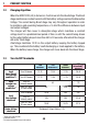
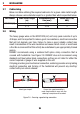
1.4 Error Codes
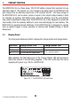
In the event of a fault with the unit installation, either battery or solar panel, ALL
the LEDs on the unit will fl ash to indicate the fault type. Flashing sequences are
described in the table below.
LED State Description
1 fl ash (1 fl ash followed by 3.5 second off) Internal Hardware Fault
2 fl ash (2 fl ash followed by 3.5 second off) Reserved
3 fl ash (3 fl ash followed by 3.5 second off) Unit over temp fault
4 fl ash (4 fl ash followed by 3.5 second off) Output Battery Fault (Volts too high) /
Solar Panel connected reverse polarity
5 fl ash (5 fl ash followed by 3.5 second off) Input under voltage (Battery)
6 fl ash (6 fl ash followed by 3.5 second off) Input over voltage (Battery or Solar panel)
7 fl ash (7 fl ash followed by 3.5 second off) Reverse polarity
NOTE: The unit will operate optimally below 55°C with good airfl ow. At higher
temperatures the unit will de-rate output current.
NOTE: Appropriate connections must be made to the wires with a continuous current
rating of at least 20A for the BCDC2420(-LV). Failure to do so may cause damage to
the unit and vehicle.
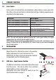
2 INSTALLATION
Mount the unit to a fl at surface close to the auxiliary
battery and away from any heat sources. The
BCDC2420(-LV) has 6 wires and should be installed
as described over the following pages.
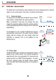
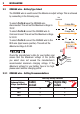
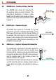
2.1 RED wire - Input Source Positive
The RED wire should be connected to the positive input
from the source - this can be either from a vehicle’s
starter battery or from a solar panel.
Appropriate size fuses should be used as per the
specifi cations table on page 2.
OR
Start
Battery
Red Wire
Midi
Fuse
Red Wire
12v
Solar
Panel